HP 4140B Operation and Service Manual - REMRSEC Facilities
HP 4140B Operation and Service Manual - REMRSEC Facilities
HP 4140B Operation and Service Manual - REMRSEC Facilities
Create successful ePaper yourself
Turn your PDF publications into a flip-book with our unique Google optimized e-Paper software.
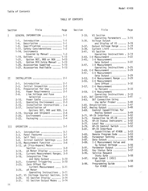
Table of Contents<br />
Model<br />
<strong>4140B</strong><br />
TABLE OF CONTENTS<br />
Sect ion Title Page<br />
I GENERAL INFORMATION ............... l-l<br />
l-l. Introduction ................ l-l<br />
l-4. Description ................. l-l<br />
1-9. Specification ............... 1-2<br />
l-11, Safety Considerations ....... 1-2<br />
1-14. Instruments<br />
Covered by <strong>Manual</strong> ......... l-3<br />
1-19. Options .................... 1-13<br />
1-21. Option 907, 908 or 909 ... 1-13<br />
l-23. Option 910 Extra <strong>Manual</strong> . . 1-13<br />
l-25. Accessories Supplied ....... 1-13<br />
l-27. Accessories Available ...... 1-13<br />
II INSTALLATION ...................... 2-1<br />
2-l. Introduction ................ 2-l<br />
2-3. Initial Inspection .......... 2-l<br />
2-5. Preparation for Use ......... 2-l<br />
2-6. Power Requirements ........ 2-l<br />
2-8. Line Voltage <strong>and</strong> Fuse<br />
Selection ............... 2-1<br />
2-10. Power Cable ............... 2-3<br />
2-12. Operating Environment ..... 2-3<br />
2-15. Installation Instructions . 2-4<br />
2-17. Installation of<br />
Options 907, 908 <strong>and</strong> 909. 2-4<br />
2-19. Storage <strong>and</strong> Shipment ........ 2-4<br />
2-20. Environment ............... 2-4<br />
2-22. Packaging ................. 2-4<br />
III OPERATION ......................... 3-l<br />
ii<br />
3-l. Introduction ................ 3-1<br />
3-3. Panel Features .............. 3-l<br />
3-5. Self Test ................... 3-l<br />
3-8. Initial Control Settings .... 3-8<br />
3-10. Measurement Function ........<br />
3-12. pA (Pica-Ampere) Meter<br />
3-8<br />
Section ................... 3-9<br />
3-14. pA Meter Display .......... 3-9<br />
3-16. Current Measurement Ranges. 3-9<br />
3-18. Integration Time<br />
<strong>and</strong> Data Output ........ 3-10<br />
3-21. External Triggering ...... 3-10<br />
3-23. Zero Offset for<br />
Current Measurement .... 3-11<br />
3-25. pA Meter<br />
Operating Instructions . 3-11<br />
3-27. VS (Voltage Source) Section. 3-14<br />
3-29. VS Section Display ....... 3-14<br />
3-31. VS Section Output Modes . . 3-14<br />
Section Title Page<br />
3-33. VS Section<br />
Operating Parameters . . . 3-15<br />
3-35. Voltage Output<br />
<strong>and</strong> Display of VS . . . . . . 3-15<br />
3-37. Output Voltage Range . . . . . 3-19<br />
3-39. Current Limit . . . . . . . . . . . . 3-19<br />
3-41. VS Section<br />
Operating Instructions . 3-19<br />
3-43. I-V Measurement . . . . . . . . . . . . 3-22<br />
3-45.~ I-V Measurement<br />
Data Output . . . . . . . . . . . . 3-22<br />
3-47. I-V Measurement<br />
Operating Instructions . 3-25<br />
3-49. C-V Measurement . . . . . . . . . . . . 3-29<br />
3-51. C-V Measurement<br />
Data Output . . . . . . . . . . . . 3-29<br />
3-53. C-V Measurement Range . . . . 3-29<br />
3-55. C-V Measurement<br />
Zero Offset . . . . . . . . . . . . 3-32<br />
3-57. C-V Measurement<br />
in Percent . . . . . . . . . . . . . 3-33<br />
3-59. C-V Measurement<br />
Operating Instruct ions . 3-33<br />
3-61. DUT Connection . . . . . . . . . . . . . 3-41 _<br />
3-63. DUT Connection Using<br />
3-65.<br />
3-67.<br />
3-69.<br />
3-71.<br />
3-73.<br />
3-75.<br />
3-77.<br />
3-79.<br />
3-81.<br />
3-83.<br />
3-85.<br />
3-87.<br />
3-89.<br />
3-91.<br />
3-93.<br />
3-95.<br />
3-97.<br />
3-99.<br />
the Wafer Prober ....... 3-44<br />
Annunciations .............. 3-47<br />
Analog Output .............. 3-49<br />
Control Capabilities for<br />
Analog Output .......... 3-49<br />
<strong>HP</strong>-IB Interface ............ 3-52<br />
Connection to <strong>HP</strong>-IB ...... 3-52<br />
<strong>HP</strong>-IB Status Indicators . . 3-52<br />
Local Key . . . . . . . . . . . . . . . . 3-52<br />
<strong>HP</strong>-IB Control Switch . . . . . 3-52<br />
<strong>HP</strong>-IB Interface<br />
Capabilities of <strong>4140B</strong> . . 3-53<br />
Remote Program Code . . . . . . 3-53<br />
Parameter Setting . . . . . . . . 3-56<br />
Data Output . . . . . . . . . . . . . . 3-56<br />
1-C Measurement Value <strong>and</strong><br />
VA Output Voltage . . . . . . 3-56<br />
Parameter Output . . . . . . . . . 3-57<br />
Key Status Data . . . . . . . . . . 3-57<br />
<strong>Service</strong> Request<br />
Statu Byte . . . . . . . . . . . . . 3-58<br />
High Speed I (HSI)<br />
Function . . . . . . . . . . . . . . . 3-58<br />
Programming Guide<br />
for <strong>4140B</strong> . . . . . . . . . . . . . . 3-60


