Cover/Back.preflight (Page 2) - Siemens
Cover/Back.preflight (Page 2) - Siemens
Cover/Back.preflight (Page 2) - Siemens

You also want an ePaper? Increase the reach of your titles
YUMPU automatically turns print PDFs into web optimized ePapers that Google loves.
Electrostatic Shielded<br />
Electrical noise and transients on power<br />
lines can be created by a number of<br />
different sources. Some examples are:<br />
lightning strikes, switching or motor<br />
loads or capacitors, and SCR circuits.<br />
Electrical noise can be classified as<br />
either “common” or “transverse”<br />
mode. Common-mode noise is the<br />
type which appears between the line<br />
conductor and ground, whereas transverse-mode<br />
noise appears between<br />
two line conductors. These types of<br />
noise have been around since electricity<br />
was first used. However, they were of<br />
little concern where traditional electromechanical<br />
devices were used.<br />
But today, electronic components and<br />
systems are being used increasingly in<br />
many types of equipment destined for<br />
commercial and industrial installations.<br />
Electronic circuitry can be sensitive to<br />
transient noise and these transients<br />
have to be controlled.<br />
Transient noise is usually measured<br />
in decibels (dB). Decibel is a unit of<br />
measurement, in this context, used<br />
to express the ratio between the input<br />
transient voltage and the output transient<br />
voltage.<br />
Noise Attenuation (dB) =<br />
V in<br />
20 log 10 V out<br />
The formula used in measurement of<br />
transient noise attenuation is logarithmic<br />
and hence a change of 40 dB to<br />
60 dB is actually a ten fold reduction<br />
in electrical noise.<br />
The following table outlines some<br />
common attenuating ratios and their<br />
decibel equivalents.<br />
Voltage Ratio Transient Noise<br />
V in : V out Attenuation (dB) ➀<br />
5:1 14<br />
10:1 20<br />
100:1 40<br />
1,000:1 60<br />
10,000:1 80<br />
100,000:1 100<br />
1,000,000:1 120<br />
➀ Common mode.<br />
Single Phase - Electrostatic Shielded ➀<br />
208 277 480 240x480 600<br />
KVA 120/240 120/240 120/240 120/240 120/240<br />
3 1B1N003ES 1E1R003ES 1F1R003ES 1D1N003ES 1G1R003ES<br />
5 1B1N005ES 1E1R005ES 1F1R005ES 1D1N005ES 1G1R005ES<br />
7.5 1B1N007ES 1E1R007ES 1F1R007ES 1D1N007ES 1G1R007ES<br />
10 1B1N010ES 1E1R010ES 1F1R010ES 1D1N010ES 1G1R010ES<br />
15 1B1N015ES 1E1R015ES 1F1R015ES 1D1N015ES 1G1R015ES<br />
25 1D1Y025ES 1G1U025ES<br />
37.5 1D1Y037ES 1G1U037ES<br />
50<br />
1D1Y050ES 1G1U050ES<br />
75<br />
— — —<br />
1D1Y075ES 1G1U075ES<br />
100 1D1Y100ES 1G1U100ES<br />
167 1D1Y167ES 1G1U167ES<br />
Three Phase - Electrostatic Shielded ➀<br />
208∆ 208∆ 480∆ 480∆ 480∆<br />
KVA 208Y/120 480Y/277 208Y/120 240∆ 480Y/277<br />
3 3F3R003ES 3F2R003ES<br />
6 — — 3F3R006ES 3F2R006ES —<br />
9 3F3R009ES 3F2R009ES<br />
15 3B3Y015ES 3B5Y015ES 3F3Y015ES 3F1Y015ES 3F5Y015ES<br />
30 3B3Y030ES 3B5Y030ES 3F3Y030ES 3F1Y030ES 3F5Y030ES<br />
45 3B3Y045ES 3B5Y045ES 3F3Y045ES 3F1Y045ES 3F5Y045ES<br />
75 3B3Y075ES 3B5Y075ES 3F3Y075ES 3F1Y075ES 3F5Y075ES<br />
112.5 3B3Y112ES 3B5Y112ES 3F3Y112ES 3F1Y112ES 3F5Y112ES<br />
150 3B3Y150ES 3B5Y150ES 3F3Y150ES 3F1Y150ES 3F5Y150ES<br />
225 3B5S225ES 3F3Y225ES 3F1Y225ES 3F5Y225ES<br />
300 — 3B5S300ES 3F3Y300ES 3F1Y300ES 3F5Y300ES<br />
500 3B5S500ES 3F3Y500ES 3F1Y500ES 3F5Y500ES<br />
➀ Refer to page 5 for other optional modifications.<br />
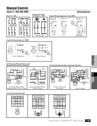
An optional feature for isolation transformers<br />
is to include an electrostatic<br />
shield between the primary and<br />
secondary windings. Shielded isolation<br />
transformers do not provide voltage<br />
regulation, but they do reduce electrical<br />
noise by attenuating spikes and<br />
transients to ground. The amount of<br />
transient noise attenuation depends<br />
on the transformer design, but a<br />
typical or “standard” shielded isolation<br />
transformer will provide about 60 dB<br />
attenuation (10 KHz -10 MHz). Shielded<br />
isolation transformers are typically used<br />
where load equipment is sensitive to<br />
transients or to suppress transients<br />
from back-feeding onto the feeder<br />
circuits.<br />
Unshielded Transformer<br />
Primary<br />
Shielded Transformer<br />
V<br />
Primary<br />
V<br />
Secondary<br />
Secondary<br />
11