The Naim Balanced Mode Radiator - Naim Audio
The Naim Balanced Mode Radiator - Naim Audio
The Naim Balanced Mode Radiator - Naim Audio

Create successful ePaper yourself
Turn your PDF publications into a flip-book with our unique Google optimized e-Paper software.
1<br />
<strong>The</strong> <strong>Naim</strong> <strong>Balanced</strong> <strong>Mode</strong> <strong>Radiator</strong><br />
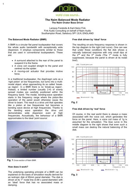
<strong>The</strong> <strong>Naim</strong> Ovator Bass Driver<br />
Lampos Ferekidis & Karl-Heinz Fink<br />
Fink <strong>Audio</strong> Consulting on behalf of <strong>Naim</strong> <strong>Audio</strong><br />
Southampton Road, Salisbury SP1 2LN, ENGLAND<br />
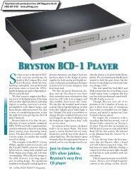
<strong>The</strong> <strong>Balanced</strong> <strong>Mode</strong> <strong>Radiator</strong> (BMR)<br />
A BMR is a circular flat panel loudspeaker that covers<br />
the whole audio bandwidth with exceptionally wide<br />
dispersion. It employs components similar to those<br />
that are used in conventional loudspeakers. <strong>The</strong>se<br />
are:<br />
• A surround attached to the rear of the panel to<br />
suspend it to the frame.<br />
• A voice coil coupled straight to the panel and<br />
centred via the spider.<br />
• A moving-coil actuator that provides motive<br />
force.<br />
In a traditional loudspeaker, the diaphragm acts as a<br />
‘rigid piston’ at low frequencies, but turns into a multimodal<br />
object, when approaching its so called ‘breakup<br />
region’. In a BMR there is no ‘break-up region’.<br />
Instead, a limited number (usually 2-4) of evenly<br />
spread modes are carefully positioned within the<br />
frequency band. <strong>The</strong> modal, bending-wave operation<br />
starts in the frequency range where the piston-like<br />
operation of the panel would otherwise cause the<br />
driver to beam. <strong>The</strong> result is a drive unit that operates<br />
like a piston at low frequencies but becomes a<br />
bending wave device at high frequencies. Thanks to<br />
the bending wave operation the drive unit<br />
demonstrates wide dispersion even at high<br />
frequencies. Acoustically, the behaviour of a BMR<br />
approximates to the ideal ‘point source’.<br />
panel<br />
Free disk driven by ‘ideal’ force<br />
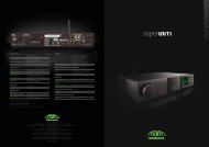
<strong>The</strong> resulting on-axis frequency response is shown in<br />
the top diagram to the right (red curve). One can see<br />
that under these conditions the flat disk shows a<br />
naturally balanced response with only small dips at<br />
the 2 nd and the 3 rd mode (<strong>The</strong> 1 st mode is fully<br />
suppressed, because the panel is driven at its nodal<br />
line!).<br />
100<br />
90<br />
80<br />
70<br />
60<br />
50<br />
Fig. 2<br />
(dB) Sound pressure<br />
100 200 500 1k M voice 2k coil = 5k 10k 20k<br />
Frequency (Hz)<br />
Mvoicecoil = 0g<br />
Free disk driven by ‘real’ force<br />
Of course, in the real world there is always a mass<br />
associated with the voice coil, which generates the<br />
force on the panel. Here, a voice coil mass of 1g is<br />
assumed for the simulation. <strong>The</strong> blue curve in the<br />
middle diagram to the right shows that even such a<br />
small mass can destroy the natural balancing of the<br />
disk.<br />
100<br />
(dB) Sound pressure<br />
surround<br />
voice coil<br />
magnet<br />
spider<br />
90<br />
80<br />
70<br />
Fig. 1 Cross-section of <strong>Naim</strong> BMR<br />
How does it work<br />
<strong>The</strong> underlying operating principle of a BMR can be<br />
explained on the basis of simulation results derived for<br />
an isotropic disk of 85mm panel diameter. <strong>The</strong> disk is<br />
driven at its 1 st nodal line (0.68 x panel-diameter) with<br />
an ‘ideal’ force that has no associated mass or<br />
damping.<br />
60<br />
M voice coil =<br />
50<br />
100 200 500 1k 2k 5k 10k 20k<br />
Frequency (Hz)<br />
Mvoicecoil = 0g<br />
Mvoicecoil = 1g<br />
Fig. 3
2<br />
<strong>Balanced</strong> disk driven by ‘real’ force<br />
Now, additional masses are placed left and right of the<br />
voice coil at pre-determined diameters. <strong>The</strong>se socalled<br />
balancing masses restore the acoustical<br />
behaviour of the free disc. Note that the masses are<br />
not normally added at the centre or the edge, since<br />
these are always anti-nodes of all modes.<br />
100<br />
90<br />
80<br />
70<br />
60<br />
50<br />
Fig. 4<br />
(dB) Sound pressure<br />
100 200 500 1k 2k 5k 10k 20k<br />
Frequency (Hz)<br />
95<br />
Mvoicecoil = 0g<br />
Mvoicecoil = 1g<br />
M voice coil<br />
= 1g<br />
Mvoicecoil = 1g + Mbal.mass<br />
From the above exercises it becomes clear that the<br />
free vibrating disk represents the acoustic reference of<br />
the BMR. It is only when a mass-carrying voice coil is<br />
attached to the disk that its previously faultless acoustic<br />
behaviour is disturbed. <strong>The</strong> original performance of<br />
a free disk can be restored by balancing the voice coil<br />
mass with additional masses. It is this operating principal<br />
that gave the “balanced mode radiator” its name.<br />
(dB) Level dB, Voltage Sensitivity<br />
Technical Aspects<br />
Conventional loudspeaker<br />
Evaluation is a fundamental part of the creation of any<br />
new loudspeaker. Traditionally, a uniform response<br />
over the audible range has been an obvious aim for<br />
the designer. This is usually verified by acquiring the<br />
on-axis response together with one or two off-axis<br />
responses. <strong>The</strong> on-axis response is measured in front<br />
of the loudspeaker level with the tweeter at a distance<br />
of 1 to 2m. <strong>The</strong> off-axis responses are measured at a<br />
similar height except that the microphone is rotated to<br />
a distinct angle (e.g. 15°, 30° …). When dealing with<br />
conventional drive units this method is sufficient since<br />
the on- and off-axis responses look very much alike,<br />
except for the level which drops constantly with<br />
increasing measuring angle.<br />
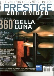
Fig. 5 and 6 show response curves for a typical 2-way<br />
loudspeaker, consisting of a 165mm bass/midrange<br />
driver and 25mm dome-tweeter. <strong>The</strong> crossover<br />
frequency is around 3.0kHz. Figure 5 shows selected<br />
frequency response curves at 0°, 30°, 60° and 90°.<br />
Figure 6 shows the horizontal frequency/directivity<br />
plot, where the level is colour-coded and plotted over<br />
frequency against measuring angle (range -90° –<br />
+90°).<br />
<strong>The</strong> frequency/directivity plot reveals that with<br />
increasing frequency the 165mm bass/midrange<br />
driver starts projecting the sound more to the front.<br />
When the tweeter takes over at around 3.0 kHz the<br />
directivity widens again until the tweeter itself<br />
becomes directional above 8.0 kHz. <strong>The</strong> general<br />
characteristic of the frequency response under various<br />
angles remains unchanged, so that the on-axis<br />
frequency response gives already a good indication of<br />
the tonal balance of the loudspeaker.<br />
90<br />
85<br />
80<br />
75<br />
70<br />
65<br />
60<br />
55<br />
50<br />
45<br />
200 500 1k<br />
2k 5k 10k<br />
20k<br />
Fig. 5 On- and off-axis SPL of 2-way speaker @ 0° , 30° , 60° , 90° .<br />
Frequency (Hz)
3<br />
(deg) Axial angle<br />
Voltage Sensitivity, Level dB (dB)<br />
90<br />
75<br />
60<br />
45<br />
30<br />
15<br />
0<br />
-15<br />
-30<br />
-45<br />
-60<br />
-75<br />
-90<br />
200 500 1k<br />
2k 5k 10k<br />
20k<br />
Frequency (Hz)<br />
Fig. 6<br />
90<br />
88<br />
86<br />
84<br />
82<br />
80<br />
78<br />
76<br />
74<br />
72<br />
70<br />
68<br />
66<br />
64<br />
62<br />
60<br />
58<br />
56<br />
54<br />
52<br />
50
4<br />
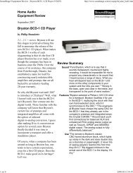
<strong>Balanced</strong> <strong>Mode</strong> <strong>Radiator</strong><br />
In Fig. 7 and 8 the on and off-axis responses and<br />
frequency/directivity plot the are shown for the <strong>Naim</strong><br />
BMR. From the colour-coded directivity plot one can<br />
see that the BMR radiates much more broadly than<br />
the 2-way loudspeaker discussed above. Due to its<br />
combination of piston-like operation at low frequencies<br />
and bending wave radiation at higher frequencies, the<br />
drive unit sustains a very broad radiation<br />
characteristic up to 25.0 kHz. Even at 90° measuring<br />
angle the high-frequency level remains only 10dB<br />
below the on-axis reference level.<br />
Since the BMR unit can operate down to 100 Hz, the<br />
system designer is free to choose a crossover<br />
frequency that fulfils the requirements of the cabinet<br />
geometry and the low frequency driver.<br />
What is more important however is that the on-axis<br />
frequency response curve is no longer an accurate<br />
indicator for the tonality of the loudspeaker. In fact<br />
during the development of the <strong>Naim</strong> BMR it became<br />
clear that the on-axis response is as good, or bad, as<br />
any other single frequency response measured at any<br />
arbitrary angle.<br />
95<br />
(dB) Level dB, Voltage Sensitivity<br />
Fig. 7<br />
90<br />
85<br />
80<br />
75<br />
70<br />
65<br />
60<br />
55<br />
50<br />
45<br />
200 500 1k<br />
2k 5k 10k<br />
20k<br />
On- and off-axis SPL of 2-way speaker @ 0° , 30° , 45° , 60° .<br />
Frequency (Hz)<br />
(deg) Axial angle<br />
Voltage Sensitivity (dB)<br />
90<br />
75<br />
60<br />
45<br />
30<br />
15<br />
0<br />
-15<br />
-30<br />
-45<br />
-60<br />
-75<br />
-90<br />
200 500 1k<br />
2k 5k 10k<br />
20k<br />
Fig. 8<br />
Frequency (Hz)<br />
90<br />
88<br />
86<br />
84<br />
82<br />
80<br />
78<br />
76<br />
74<br />
72<br />
70<br />
68<br />
66<br />
64<br />
62<br />
60<br />
58<br />
56<br />
54<br />
52<br />
50
5<br />
So what is a meaningful measure for a BMR<br />
<strong>The</strong>re is a contradiction. A smooth on-axis response is<br />
desirable, since it defines the tonality of the direct<br />
sound when sitting in the near field of the<br />
loudspeaker. But the BMR’s broad radiation makes it<br />
necessary that the off-axis radiation should be free of<br />
any strong side-lobes, otherwise the sound reflected<br />
back of the sidewalls or ceiling will cause audible<br />
colorations.<br />
Thus for a BMR-based loudspeaker it is necessary to<br />
measure both the horizontal and vertical frequency<br />
dispersion and the acoustic power. <strong>The</strong> acoustic<br />
power (or sound power) response describes the total<br />
acoustic energy the loudspeaker radiates into the<br />
room. It is the only measure that can be used to<br />
characterise loudspeakers with broad dispersion or a<br />
large radiating area – like large dipole loudspeakers,<br />
omni-directional loudspeakers or BMR-based<br />
loudspeakers. A meaningful assessment of a BMRbased<br />
system can only be performed on the basis of a<br />
range of measurements, including the on-axis<br />
response, the acoustic power response and<br />
dispersion data acquired for the horizontal and vertical<br />
plane.<br />
It is obvious that the acquisition of these data takes<br />
more time than the measurement of a single response<br />
curve. Consequently the development time for a BMR<br />
is considerably longer than the time required for a<br />
conventional cone-based woofer or dome-tweeter,<br />
since each step in the development cycle needs to be<br />
verified by all the above mentioned measurements.<br />
<strong>The</strong> Ovator S-600 and what is so special about it<br />
As one could guess from the above the <strong>Naim</strong> BMR<br />
has come a long way. In fact, the development of the<br />
BMR took more than three years. Every part has<br />
undergone an extensive evaluation regarding its<br />
influence on the sound. This includes the motor, the<br />
membrane (panel), the surround, the voice coil and<br />
the spider.<br />
<strong>The</strong> motor<br />
Although the unit operates only above 400 Hz and<br />
thus will experience excursion values of less than<br />
1mm, the motor was intensively optimised using finiteelement-analysis<br />
(FEA). Several aspects needed to<br />
be addressed during the development. First of all, the<br />
motor has to generate a certain amount of magnetic<br />
flux density in the air gap. Together with the voice coil,<br />
the flux density determines the final sensitivity of the<br />
drive unit. Another requirement for the motor was that<br />
it should not interfere acoustically with the sound<br />
radiated to the rear. Thus a very compact form factor<br />
was mandatory. Furthermore the motor should<br />
provide sufficient cooling so that the voice coil’s<br />
operating temperature remains low. This prevents the<br />
driver from running into thermal compression.<br />
Fig. 9 Cross-section view of <strong>Balanced</strong> <strong>Mode</strong> <strong>Radiator</strong>.
6<br />
Fig. 10 Flux density plot of BMR magnet system<br />
<strong>The</strong> final motor consists of a double neodymium<br />
magnet configuration positioned inside the voice coil.<br />
Neodymium was chosen because of its ten-time<br />
higher energy product compared to ferrite. This allows<br />
for a very compact design with the two magnets<br />
placed above and below the pole piece. From a<br />
magnetic point of view the metal u-cup could have<br />
been smaller, but the deep shape assures a high<br />
thermal capacity so that heat is quickly dissipated<br />
from the voice coil into the metal avoiding thermal<br />
saturation of the metal part. A copper shield that<br />
covers the pole piece helps to reduce distortions but<br />
also controls the amount of high frequency output,<br />
due to its influence on the impedance.<br />
<strong>The</strong> voice coil mass represents a crucial design<br />
variable in a BMR-design. <strong>The</strong> lower the mass, the<br />
less additional balancing masses are required. Thus<br />
the coil is wound from copper-clad-aluminium instead<br />
of pure copper.<br />
After evaluating a range of possible former materials<br />
the final choice was made in favour of glass fibre,<br />
which turned out to give the best sounding result.<br />
Technically its good heat-resistance and very good<br />
stiffness make it an ideal choice of a BMR.<br />
<strong>The</strong> membrane (panel)<br />
<strong>The</strong> surround<br />
In a conventional cone-based drive unit the<br />
suspension fulfils two functions. At low frequencies it<br />
serves as a suspension that controls the movement of<br />
the membrane, while at high frequencies it terminates<br />
the membrane in order to control the break-up modes.<br />
In a BMR used as pure mid/high frequency driver, the<br />
requirements are completely different. With 1mm<br />
maximum excursion, there is no need to control the<br />
movement at low frequencies and when the panel<br />
becomes modal, the surround acts as a balancing<br />
mass. Thus the weight, diameter and damping of the<br />
surround is chosen such that good control for all<br />
bending modes, in particular the first one, is achieved.<br />
How BMR might work in more rooms<br />
Compared to conventional, more directional<br />
loudspeakers, a BMR based loudspeaker behaves<br />
differently in listening room environments. Thanks to<br />
the BMR’s consistently wider dispersion, the<br />
reverberant damping of the room will be more<br />
significant. It is helpful therefore that the room shows<br />
a consistent reverberation time, rather than a<br />
particular reverberation value. <strong>The</strong> BMR loudspeaker<br />
will also benefit from placement reasonably distant<br />
from adjacent walls.<br />
<strong>The</strong> membrane material has a large impact on the<br />
sound – if not the largest. Various panel combinations<br />
were evaluated before settling on a composite<br />
material based on a Nomex-honeycomb-core covered<br />
by paper skins on either side. This material combines<br />
low weight with good damping and high stiffness. <strong>The</strong><br />
panel’s stiffness is chosen such that the first bending<br />
mode is located in the frequency range where the<br />
panel would otherwise start to beam the sound.
7<br />
<strong>The</strong> Ovator S-600 Bass Driver<br />
Although the bass driver looks conventional from the<br />
outside, there is are numerous technical subtleties<br />
hidden within. As with the BMR motor, the 200mm<br />
bass driver motor is the result of thorough finite<br />
element analysis.<br />
<strong>The</strong> pole piece is designed to achieve very high<br />
linearity of driving force (see Fig. 11) and together<br />
with the spider’s linear suspension characteristics this<br />
guaranties extremely low distortions at low<br />
frequencies.<br />
<strong>The</strong> design also features two demodulation rings, which<br />
reduce impedance variations while the voice coil is<br />
moving and also secure low distortion figures originating<br />
from demagnetisation of metal parts due to the voice<br />
coils travelling AC-field. <strong>The</strong> large ventilation hole in the<br />
centre of the pole piece avoids air compression<br />
underneath the dust-cap and causing mechanical<br />
losses.<br />
12<br />
force factor Bl(x) [Tm]<br />
10<br />
8<br />
6<br />
4<br />
2<br />
0<br />
-10 -5 0 5<br />
10<br />
excursion x [mm], coil out =>><br />
Bl(x) - force factor Bl as function of excursion x<br />
Bl(-x) - force factor Bl as function of excursion -x<br />
Fig. 11 Measured force factor BI as function of excursion x and –x (BI(-x) illustrates the symmetry of the generated force).<br />
Fig. 12 Cross-section view of 8” <strong>Naim</strong> woofer.
8<br />
Fig. 13 Flux density plot of 8” <strong>Naim</strong> woofer.<br />
Fig. 14 Coss-section of Ovator S-600 Bass Driver<br />
<strong>The</strong> bass driver cone is long-fibre paper item with<br />
medium stiffness and was chosen to match the sound<br />
character of the BMR. Its rubber surround applies only<br />
light damping in order to avoid hysteresis effects in the<br />
suspension system and first break up mode is controlled<br />
by the shape of cone and surround instead of through<br />
the use of mechanical damping which would<br />
compromise the driver’s dynamic behaviour.<br />
Together with the closed box cabinet, the drivers<br />
achieves the target alignment of around 38 Hz with a<br />
total Q of slightly below 0.6 to guarantee the best<br />
compromise between low end extension and impulse<br />
behaviour.