SINEAX DME 440 with RS 485 interface ... - Power LabSolutions
SINEAX DME 440 with RS 485 interface ... - Power LabSolutions
SINEAX DME 440 with RS 485 interface ... - Power LabSolutions

You also want an ePaper? Increase the reach of your titles
YUMPU automatically turns print PDFs into web optimized ePapers that Google loves.
<strong>SINEAX</strong> <strong>DME</strong> <strong>440</strong> <strong>with</strong> <strong>RS</strong> <strong>485</strong> <strong>interface</strong><br />
Programmable Multi-Transducer<br />
I1<br />
I2<br />
I3<br />
L1<br />
L2<br />
L3<br />
N<br />
UH 1 2<br />
11<br />
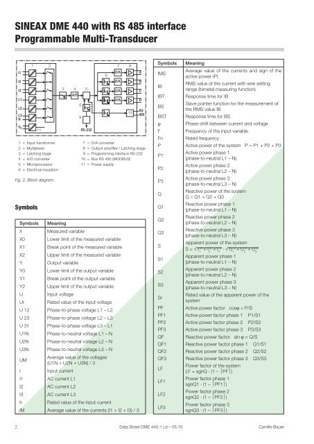
1 = Input transformer<br />
2 = Multiplexer<br />
3 = Latching stage<br />
4 = A/D converter<br />
5 = Microprocessor<br />
6 = Electrical insulation<br />
Fig. 2. Block diagram.<br />
Symbols<br />
3<br />
4 5<br />
A/D<br />
6<br />
9<br />
<strong>RS</strong>-232<br />
6<br />
7 8<br />
D/A<br />
D/A<br />
D/A<br />
D/A<br />
10<br />
A<br />
B<br />
C<br />
D<br />
<strong>RS</strong>-<br />
<strong>485</strong><br />
7 = D/A converter<br />
8 = Output amplifier / Latching stage<br />
9 = Programming <strong>interface</strong> <strong>RS</strong>-232<br />
10 = Bus <strong>RS</strong> <strong>485</strong> (MODBUS)<br />
11 = <strong>Power</strong> supply<br />
Symbols Meaning<br />
X Measured variable<br />
X0 Lower limit of the measured variable<br />
X1 Break point of the measured variable<br />
X2 Upper limit of the measured variable<br />
Y Output variable<br />
Y0 Lower limit of the output variable<br />
Y1 Break point of the output variable<br />
Y2 Upper limit of the output variable<br />
U Input voltage<br />
Ur Rated value of the input voltage<br />
U 12 Phase-to-phase voltage L1 – L2<br />
U 23 Phase-to-phase voltage L2 – L3<br />
U 31 Phase-to-phase voltage L3 – L1<br />
U1N Phase-to-neutral voltage L1 – N<br />
U2N Phase-to-neutral voltage L2 – N<br />
U3N Phase-to-neutral voltage L3 – N<br />
UM<br />
Average value of the voltages<br />
(U1N + U2N + U3N) / 3<br />
I Input current<br />
I1 AC current L1<br />
I2 AC current L2<br />
I3 AC current L3<br />
Ir Rated value of the input current<br />
IM Average value of the currents (I1 + I2 + I3) / 3<br />
Symbols Meaning<br />
2 Data Sheet <strong>DME</strong> <strong>440</strong>-1 Le – 05.10 Camille Bauer<br />
IMS<br />
Average value of the currents and sign of the<br />
active power (P)<br />
IB<br />
RMS value of the current <strong>with</strong> wire setting<br />
range (bimetal measuring function)<br />
IBT Response time for IB<br />
Slave pointer function for the measurement of<br />
BS<br />
the RMS value IB<br />
BST Response time for BS<br />
ϕ Phase-shift between current and voltage<br />
F Frequency of the input variable<br />
Fn Rated frequency<br />
P Active power of the system P = P1 + P2 + P3<br />
P1<br />
P2<br />
P3<br />
Q<br />
Q1<br />
Q2<br />
Q3<br />
S<br />
S1<br />
S2<br />
S3<br />
Active power phase 1<br />
(phase-to-neutral L1 – N)<br />
Active power phase 2<br />
(phase-to-neutral L2 – N)<br />
Active power phase 3<br />
(phase-to-neutral L3 – N)<br />
Reactive power of the system<br />
Q = Q1 + Q2 + Q3<br />
Reactive power phase 1<br />
(phase-to-neutral L1 – N)<br />
Reactive power phase 2<br />
(phase-to-neutral L2 – N)<br />
Reactive power phase 3<br />
(phase-to-neutral L3 – N)<br />
Apparent power of the system<br />
2 2 2 2 2 2<br />
S = √ I + I2 + I3 · √ U1 + U2 + U3<br />
1<br />
Apparent power phase 1<br />
(phase-to-neutral L1 – N)<br />
Apparent power phase 2<br />
(phase-to-neutral L2 – N)<br />
Apparent power phase 3<br />
(phase-to-neutral L3 – N)<br />
Sr<br />
Rated value of the apparent power of the<br />
system<br />
PF Active power factor cosϕ = P/S<br />
PF1 Active power factor phase 1 P1/S1<br />
PF2 Active power factor phase 2 P2/S2<br />
PF3 Active power factor phase 3 P3/S3<br />
QF Reactive power factor sin ϕ = Q/S<br />
QF1 Reactive power factor phase 1 Q1/S1<br />
QF2 Reactive power factor phase 2 Q2/S2<br />
QF3 Reactive power factor phase 3 Q3/S3<br />
LF<br />
LF1<br />
LF2<br />
LF3<br />
<strong>Power</strong> factor of the system<br />
LF = sgnQ · (1 – ⏐PF⏐)<br />
<strong>Power</strong> factor phase 1<br />
sgnQ1 · (1 – ⏐PF1⏐)<br />
<strong>Power</strong> factor phase 2<br />
sgnQ2 · (1 – ⏐PF2⏐)<br />
<strong>Power</strong> factor phase 3<br />
sgnQ3 · (1 – ⏐PF3⏐)