Steel Bridge Bearing Selection and Design Guide (Part 3)
Steel Bridge Bearing Selection and Design Guide (Part 3)
Steel Bridge Bearing Selection and Design Guide (Part 3)

You also want an ePaper? Increase the reach of your titles
YUMPU automatically turns print PDFs into web optimized ePapers that Google loves.
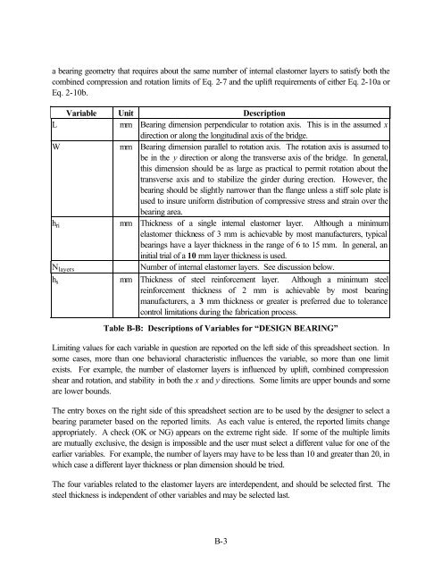
a bearing geometry that requires about the same number of internal elastomer layers to satisfy both the<br />
combined compression <strong>and</strong> rotation limits of Eq. 2-7 <strong>and</strong> the uplift requirements of either Eq. 2-10a or<br />
Eq. 2-10b.<br />
Variable Unit Description<br />
L<br />
mm <strong>Bearing</strong> dimension perpendicular to rotation axis. This is in the assumed x<br />
direction or along the longitudinal axis of the bridge.<br />
W<br />
mm <strong>Bearing</strong> dimension parallel to rotation axis. The rotation axis is assumed to<br />
be in the y direction or along the transverse axis of the bridge. In general,<br />
this dimension should be as large as practical to permit rotation about the<br />
transverse axis <strong>and</strong> to stabilize the girder during erection. However, the<br />
bearing should be slightly narrower than the flange unless a stiff sole plate is<br />
used to insure uniform distribution of compressive stress <strong>and</strong> strain over the<br />
bearing area.<br />
h ri<br />
mm Thickness of a single internal elastomer layer. Although a minimum<br />
elastomer thickness of 3 mm is achievable by most manufacturers, typical<br />
bearings have a layer thickness in the range of 6 to 15 mm. In general, an<br />
initial trial of a 10 mm layer thickness is used.<br />
N layers<br />
Number of internal elastomer layers. See discussion below.<br />
h s mm Thickness of steel reinforcement layer. Although a minimum steel<br />
reinforcement thickness of 2 mm is achievable by most bearing<br />
manufacturers, a 3 mm thickness or greater is preferred due to tolerance<br />
control limitations during the fabrication process.<br />
Table B-B: Descriptions of Variables for “DESIGN BEARING”<br />
Limiting values for each variable in question are reported on the left side of this spreadsheet section. In<br />
some cases, more than one behavioral characteristic influences the variable, so more than one limit<br />
exists. For example, the number of elastomer layers is influenced by uplift, combined compression<br />
shear <strong>and</strong> rotation, <strong>and</strong> stability in both the x <strong>and</strong> y directions. Some limits are upper bounds <strong>and</strong> some<br />
are lower bounds.<br />
The entry boxes on the right side of this spreadsheet section are to be used by the designer to select a<br />
bearing parameter based on the reported limits. As each value is entered, the reported limits change<br />
appropriately. A check (OK or NG) appears on the extreme right side. If some of the multiple limits<br />
are mutually exclusive, the design is impossible <strong>and</strong> the user must select a different value for one of the<br />
earlier variables. For example, the number of layers may have to be less than 10 <strong>and</strong> greater than 20, in<br />
which case a different layer thickness or plan dimension should be tried.<br />
The four variables related to the elastomer layers are interdependent, <strong>and</strong> should be selected first. The<br />
steel thickness is independent of other variables <strong>and</strong> may be selected last.<br />
B-3