Pneuma-Seal Brochure - Seals Unlimited
Pneuma-Seal Brochure - Seals Unlimited
Pneuma-Seal Brochure - Seals Unlimited

Create successful ePaper yourself
Turn your PDF publications into a flip-book with our unique Google optimized e-Paper software.
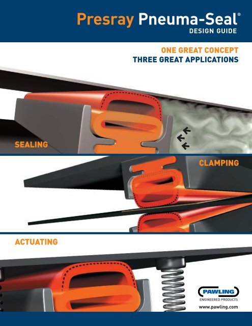
Presray <strong>Pneuma</strong>-<strong>Seal</strong>®<br />
DESIGN GUIDE<br />
ONE GREAT CONCEPT<br />
THREE GREAT APPLICATIONS<br />
SEALING<br />
CLAMPING<br />
ACTUATING<br />
ENGINEERED PRODUCTS<br />
www.pawling.com
<strong>Pneuma</strong>-<strong>Seal</strong><br />
The Solution to <strong>Seal</strong>ing<br />
1. Horizontal or Vertical sliding doors.<br />
2. Hinged doors with flush thresholds for easy personnel<br />
or equipment access.<br />
3. Large fabricated doors or other closures<br />
where it is impractical to machine the sealing surfaces to<br />
accommodate conventional seals and gaskets.<br />
4. Processing equipment where rapid sealing and unsealing<br />
is required.<br />
Doors and other closures can be positively sealed by using<br />
<strong>Pneuma</strong>-<strong>Seal</strong>. The seal is inflated with air or other fluid by a<br />
pressure-regulated supply system (which can also be furnished<br />
by us). When pressurized, the seal conforms to uneven surfaces<br />
and provides an efficient, reliable barrier to dust, moisture,<br />
contaminants, and/or pressure differential. Operating pressures<br />
are usually in the range of 10 to 35 PSI but some of the seals can<br />
be designed to operate at lower pressures, in the order of 5 PSI<br />
or less, or at higher pressures of 100 PSI or more. Expansion<br />
capabilities, the ability to close a "gap", vary from cross section<br />
to cross section. Large "gaps" may be accommodated but it<br />
should be noted that as the gap increases, the pressure required<br />
to seal against a given pressure differential increases, thereby<br />
decreasing the seal’s flex life.<br />
The Solution to Clamping and Actuating<br />
<strong>Pneuma</strong>tic Clamps<br />
When inflated, the clamp provides uniform controlled pressure to firmly clamp<br />
pieces together during bonding operations or to hold pieces in place during<br />
machining or cutting operations. Typical applications include the bonding of<br />
airframe components and stopping large pharmaceutical bottles on a<br />
conveyor line.<br />
<strong>Pneuma</strong>tic Actuators<br />
The expanding <strong>Pneuma</strong>-<strong>Seal</strong> moves and repositions other components which exert<br />
pressure to actuate switching devices, to open and close air or hydraulic passages,<br />
or to clamp mechanical components. In a typical application, the pressurized<br />
<strong>Pneuma</strong>-<strong>Seal</strong> effects the desired motion and mechanical springs return the<br />
components to their normal open or closed position.<br />
<strong>Pneuma</strong>-<strong>Seal</strong> Construction<br />
<strong>Pneuma</strong>-<strong>Seal</strong> is available in four different types of<br />
construction:<br />
• Extruded with vulcanized joints or ends<br />
• Extruded and either fully preformed or with preformed corners,<br />
with vulcanized joints or ends<br />
• Fully molded, seamless (no vulcanized joints)<br />
• Fully molded, seamless (no vulcanized joints), and reinforced with<br />
Nylon, Nomex ® , Kevlar ® , fiberglass or Dacron ® fabric<br />
The extruded construction seals are offered for applications where<br />
economy is of primary concern. However, in applications involving<br />
high pressure and/or repeated, continuous use, where safety and<br />
reliability are of major importance, the molded fabric-reinforced<br />
construction is recommended. The molding process minimizes weak<br />
points at "spliced" joints and the fabric reinforcing gives additional<br />
structural integrity assuring better resistance to rupture and tear,<br />
thereby providing superior flex life.<br />
2
www.pawling.com<br />
Presray <strong>Pneuma</strong>-<strong>Seal</strong><br />
Pawling Engineered Products is a vertically integrated business designing, selling and manufacturing the inflatable<br />
<strong>Pneuma</strong>-<strong>Seal</strong> ® product line and other custom rubber products of Presray Corporation as well as the compounds and<br />
rubber and plastic extrusions of Pawling Corporation.<br />
This new Design Guide is filled with information, which should prove valuable to you when working with new or changing<br />
requirements in your business. Please give us a call at 845-855-1000 with questions on how our capabilities might help<br />
solve problems for your specific application.<br />
Table of Contents<br />
The Solution to <strong>Seal</strong>ing ...................................................................................................................2<br />
Applications .....................................................................................................................................4<br />
Applications in Detail ......................................................................................................................5<br />
Typical Configurations.....................................................................................................................6<br />
Materials..........................................................................................................................................7<br />
Type 1 <strong>Pneuma</strong>-<strong>Seal</strong> ......................................................................................................................8<br />
Retention Systems for Type 1..................................................................................................9<br />
Type 2 <strong>Pneuma</strong>-<strong>Seal</strong> ....................................................................................................................10<br />
Type 3 <strong>Pneuma</strong>-<strong>Seal</strong> ....................................................................................................................11<br />
Retention Systems for Type 3................................................................................................12<br />
Type 4 <strong>Pneuma</strong>-<strong>Seal</strong> ....................................................................................................................12<br />
Type 10 <strong>Pneuma</strong>-<strong>Seal</strong> ..................................................................................................................13<br />
Retention Groove Design for Type 10 ....................................................................................13<br />
Type 7 <strong>Pneuma</strong>-<strong>Seal</strong> ....................................................................................................................14<br />
Other <strong>Pneuma</strong>-<strong>Seal</strong> Types...........................................................................................................14<br />
<strong>Seal</strong>ing Small Diameters.............................................................................................................14<br />
2-Piece <strong>Seal</strong>s ................................................................................................................................15<br />
End Configurations.......................................................................................................................15<br />
Mechanical Interlocking Ends ...............................................................................................15<br />
End Configurations for Types 1 and 2 <strong>Seal</strong>s .........................................................................15<br />
End Configurations for Type 3 <strong>Seal</strong>s .....................................................................................16<br />
End Configurations and Clamps for Type 10 <strong>Seal</strong>s...............................................................16<br />
Corner Configurations .................................................................................................................17<br />
<strong>Seal</strong>ing Rectangular Openings with Radially Outward Expanding <strong>Seal</strong>s.............................17<br />
Air Connections ............................................................................................................................18<br />
Air Connections for Types 1,2,3,4 and 7................................................................................18<br />
End Connections for Types 1,2,3,4 and 7 ..............................................................................19<br />
Air Connections for Type 10 <strong>Seal</strong>s ........................................................................................19<br />
Custom Rubber Fabrications.......................................................................................................20<br />
Special Molded Cross Sections .............................................................................................21<br />
Fabric Reinforced Compression <strong>Seal</strong>s ..................................................................................21<br />
Compression Gaskets, Trim, Channels, Bumpers, and Other Non-Inflatable Profiles ...22 & 23<br />
3
<strong>Pneuma</strong>-<strong>Seal</strong><br />
Applications<br />
Pawling Engineered Products specializes in the custom design and manufacture of inflatable rubber products,<br />
seals, and other engineered rubber devices. We will carefully analyze your problem, apply our extensive<br />
technical knowledge, and follow your project through to an efficient solution. Advanced compounding, molding,<br />
extruding, fabricating, coupled with testing equipment and processes enable us to address your most<br />
demanding needs for rubber fabrications that require a high level of durability and reliability.<br />
Powder & Bulk Solids<br />
Processing Equipment:<br />
Mixers, blenders,<br />
screeners, dryers, chutes,<br />
hoppers, valves<br />
Transportation:<br />
High speed trains,<br />
tailgate seals, automobile<br />
emission control test<br />
sheds<br />
Nuclear:<br />
Door and hatch seals,<br />
pool gate seals,<br />
refueling seals,<br />
nozzle dam seals<br />
Electronic/Wafers<br />
Semiconductor Processing:<br />
Washers, soldering<br />
equipment, furnaces, filters,<br />
load locks, measuring<br />
equipment, actuators<br />
Medical:<br />
Virology laboratories,<br />
clean rooms, sterilizers<br />
Wineries:<br />
Lid seals for variable<br />
capacity wine tanks<br />
Paper Machinery: <strong>Seal</strong>s for<br />
the wet end of paper<br />
machinery, doctor blade<br />
bladders, inflatable bladders<br />
for expanding mandrels for<br />
slitters and scorers<br />
Aerospace/Aircraft:<br />
Wind tunnels, jet engine<br />
test cells, bladders for<br />
bonding and clamping<br />
fixtures, door and hatch<br />
seals<br />
Textile Machinery:<br />
Pressure chambers,<br />
inflatable clamps<br />
Conveyors:<br />
Conveyor stops, brakes,<br />
bumpers<br />
Converting Equipment:<br />
Access way seals<br />
Flood Protection:<br />
Gate and door seals<br />
Food Processing<br />
Equipment:<br />
Smokehouse door seals<br />
Robotics Material<br />
Handling: Clamps, grips,<br />
actuators<br />
Wood Processing:<br />
Drying kilns, log<br />
preparation<br />
chambers<br />
Marine:<br />
Cargo hatches, elevator<br />
platforms, maintenance or<br />
shut down seals on<br />
propeller shafts, personnel<br />
hatches<br />
Fluid <strong>Seal</strong>ing:<br />
Isolation valve seals,<br />
follower plate seals,<br />
maintenance shutdown<br />
shaft seals<br />
Commercial Laundry<br />
Machinery:<br />
Door seals<br />
4
www.pawling.com<br />
Applications In Detail<br />
Hopper to Transfer Cart: <strong>Pneuma</strong>-<strong>Seal</strong> on the mouth of the hopper valve or metering device<br />
expands axially down to form a leak-tight seal around the fill opening in a transfer cart.<br />
Slide Gate Valves: <strong>Pneuma</strong>-<strong>Seal</strong> provides the tightest seal possible for controlling the flow of<br />
very fine materials. The inflation and deflation of the seal is timed to coincide with the closing<br />
and opening of the slide gate.<br />
Automobile Emission Control Test Shed Door <strong>Seal</strong>s: Airtight enclosures help automotive<br />
engineers evaluate carburetor and fuel tank vent evaporative emissions. Warmed up test<br />
vehicles are pushed into hot soak enclosures. Escaping fuel vapors are measured by<br />
instruments outside the test cells. The doors to the cells are typically sealed using the Type 1<br />
<strong>Pneuma</strong>-<strong>Seal</strong> design supplied in either EPDM (EP) or Neoprene (CR).<br />
Airtight Doors: Airtight doors in virology laboratories, animal rooms, and decontamination<br />
areas are tightly sealed with <strong>Pneuma</strong>-<strong>Seal</strong>s installed around the periphery of the door to<br />
expand radially outward. This design facilitates frequent access since there is no requirement<br />
to actuate multiple dogs and there is no raised sill to obstruct personnel and equipment<br />
traffic. Pawling’s wholly-owned subsidiary, Presray, specializes in the manufacture of full<br />
airtight door assemblies. See www.fpp.presray.com for more detailed examples.<br />
Load Lock: Pawling manufactures a unique inflatable seal made of low outgassing Butyl<br />
rubber material which has been tested for vacuum service. This design provides a highly<br />
efficient and repeatable seal in the patented vacuum load lock section of a fully automated<br />
electron beam metrology system.<br />
Conveyor Stops/Brakes: <strong>Pneuma</strong>-<strong>Seal</strong> inflatable bladders represent two different ideal<br />
solutions to controlling and preventing jams on conveyor systems. Positioned alongside the<br />
product at the outer extremities of the conveyor belt (or rolls), they can be inflated against the<br />
product to temporarily interrupt the flow while the jam clears downstream. Alternately the<br />
bladders can be located underneath the product flow and activated to release the contact<br />
between belt and rollers, thereby interrupting flow while the jam clears.<br />
5
<strong>Pneuma</strong>-<strong>Seal</strong><br />
Available in Many Configurations<br />
Available in many configurations complete with required inflation connections, <strong>Pneuma</strong>-<strong>Seal</strong> requires no<br />
bonding or splicing by the user.<br />
<strong>Pneuma</strong>-<strong>Seal</strong>s (shown in a variety of cross sections on pages 8-14)<br />
can be configured to practically any shape or size. Our products<br />
can be supplied as continuous loops (Fig. 1), in strip form with<br />
sealed ends (Fig. 2), in "U" or similar shapes with preformed<br />
corners (Fig. 3), in endless configurations with preformed corners<br />
(Fig. 4), or complex configurations (Fig. 5). In many cases, a seal<br />
will conform to the corners or radii of a given installation without<br />
the necessity for preforming these corners or radii into the seal.<br />
Minimum bend radius information for circular seals, or corners on<br />
rectangular seals, is available. When requesting this data, refer to<br />
the desired cross-sections (see pages 8 to 14) and the applicable<br />
plane of use as indicated (Figs. 1, 6, 7). Arrows indicate direction of<br />
inflation.<br />
Fig. 1<br />
Fig. 2<br />
Axial Expansion<br />
Fig. 3<br />
Fig. 4<br />
Fig. 6<br />
Radial Expansion In<br />
Fig. 5<br />
Fig. 7<br />
Radial Expansion Out<br />
Many of the seals can be supplied with no joints, if required.<br />
Pawling’s unique facilities and processing techniques can produce seamless (no vulcanized joints) rubber products of virtually<br />
limitless length and size to your specifications (fabric-reinforced or non-reinforced).<br />
6
www.pawling.com<br />
<strong>Pneuma</strong>-<strong>Seal</strong> Materials<br />
<strong>Pneuma</strong>-<strong>Seal</strong> is available in a wide variety of materials as noted below, although the specific elastomers vary<br />
somewhat from one profile to another. If required, cross sections can be custom made using materials other<br />
than those indicated in this manual. Please note that the ratings given to the properties of the elastomers are<br />
based on Pawling compounds as they are applied to inflatable seals. The ratings of other manufacturers may<br />
differ as the result of compounding variables and end product use. Also note that the addition of fabric<br />
reinforcing overcomes drawbacks associated with some of the relatively poor physical characteristics of<br />
silicone, fluorosilicone, fluorocarbon rubber, and nitrile.<br />
Nitrile or<br />
Common Name — EPDM or NBR or Natural<br />
Base Polymer EP Rubber Neoprene Buna-N Rubber Butyl Silicone Fluorosilicone Fluorocarbon<br />
Ethylene Acrylonitrile Natural Isobutylene<br />
Chemical Name Propylene Chloroprene Butadiene Isoprene Isoprene Silicone Fluorosilicone Fluorocarbon<br />
ASTM Designation (ASTM D1418) EP CR NBR NR IIR VMQ FVMQ FKM<br />
Tensile Strength (psi) >2000 >2000 >2000 >2000 >2000 >1200 >1200 >1400<br />
Hardness Range (Durometer A) 40-90 20-80 50-95 50-70 40-75 40-80 40-70 70-90<br />
Tear Resistance G G F G G F P F<br />
Abrasion Resistance G to E VG G E G P F G<br />
Compression Set G G G E F VG E E<br />
Resilience Cold G G G G P E G F<br />
Resilience Hot VG VG G F VG E E E<br />
Radiation Resistance O G P F to G G G E E<br />
Impermeability to Gases G G G F O F E P<br />
Acid Resistance<br />
Mild Dilute E E F to G F to P E E E O<br />
Strong Concentrate G G F to G P G F G E<br />
Solvent Resistance<br />
Aliphatic Hydrocarbons P F to G E P P P G E<br />
Aromatic Hydrocarbons P P P P P P E E<br />
Oxygenated (Ketones, etc) G P P P G P F F<br />
Resistance To:<br />
Swelling in Lubricating Oil P G VG P P P E O<br />
Oil and Gasoline P G E P P F G E<br />
Animal Oils F F E P F G E E<br />
Water Absorption VG G VG VG VG E E E<br />
Oxidation E VG G F to P E E O G<br />
Ozone O VG F F to P F to G E O E<br />
Sunlight Aging O VG P F to P VG E E G<br />
Heat Aging VG G G G to F G O E E<br />
Low Temperature VG G F to G G G O G F<br />
Flame P G P P P F E E<br />
Vegetable Oils F G G P F P E E<br />
Chlorinated Hydrocarbons P P F P P P to F F G<br />
O = Outstanding E = Excellent VG = Very Good G = Good F = Fair P = Poor<br />
7
<strong>Pneuma</strong>-<strong>Seal</strong><br />
Type 1<br />
The “original” <strong>Pneuma</strong>-<strong>Seal</strong> and most popular inflatable profile. These cross sections are designed for ease of<br />
mechanical retention (see page 9 for options) and the “foot” allows the bulb portion to expand fully, thereby<br />
ensuring full gap optimization.<br />
Max. Gap for Max. Gap for<br />
low differential high differential<br />
pressure pressure<br />
(side load) (side load) Standard air<br />
connections<br />
Type Materials W H B Y Y (See pages 18 & 19)<br />
Non-Reinforced<br />
PRS573 EP, CR, VMQ 11/16 7/16 11/16 1/8 1/16 1A, 1B, 10, 11, 12<br />
PRS978 EP 1 1/2 3/4 1/4 3/16 1A, 1B, 10, 11, 12<br />
PRS537 EP, CR, NBR, VMQ, FKM 1 1/4 5/8 1 3/8 1/4 1A, 1B, 10, 11, 12<br />
PRS535 EP, CR, NBR, VMQ 2 7/8 1 3/4 3/4 3/8 1C, 1D, 4A, 4B, 10, 11,12<br />
PRS548 EP, CR 3 1/1/4 2 1 1/2 1C, 1D, 4A, 4B, 10, 11,12<br />
PR28925 EP 3 1/4 1 1/4 2 1 1/8 5/8 1C, 1D, 4A, 4B, 10, 11,12<br />
PRS934 CR 4 1 5/8 3 1 3/8 7/8 1C, 1D, 4A, 4B, 6, 8, 10, 11, 12<br />
Type W H B Y Y<br />
Reinforced<br />
PR13548 EP 11/16 7/16 11/16 1/8 1/16 2<br />
PRS717 EP, VMQ 1 1/2 3/4 5/16 3/16 2<br />
PRS580 EP, CR, NBR, VMQ 1 1/4 5/8 1 3/8 1/4 2<br />
PRS582 EP, CR, NBR, VMQ 2 7/8 1 3/4 3/4 1/2 3A, 3B<br />
PRS583 EP, CR, VMQ 3 1 1/4 2 1 1/4 3/4 3A, 3B<br />
PRS705 EP 4 1 5/8 3 1 3/4 1 1/4 3A, 3B<br />
PRS729 EP 5 1/2 1 5/8 4 2 1/4 1 5/8 3A, 3B<br />
PRS590 EP 7 1/4 2 1/16 4 1/8 3 2 3A, 3B<br />
Max. Gap for Max. Gap for<br />
low differential high differential<br />
pressure pressure<br />
(side load) (side load) Standard air<br />
connections<br />
Type Materials W H B Y Y (See pages 18 & 19)<br />
Non-Reinforced<br />
PRS951 EP, VMQ 1 3/16 7/8 1 13/16 5/16 3/16 10, 11, 12<br />
PR9185 EP, VMQ 1 9/16 1 1 9/16 1/2 5/16 10, 11, 12<br />
PRS946 EP 2 3/8 1 3/8 2 3/8 13/16 7/16 10, 11, 12<br />
PRS974 EP 3 1/2 2 3/16 3 1/2 1 1/8 5/8 10, 11, 12<br />
Type Materials W H B Y Y<br />
Reinforced<br />
PRS584 EP 4 1 3 1/4 2 1 1/4 3A, 3B<br />
Material availability is indicated by cross section. Please refer to page 7 for material identification. If required, cross<br />
sections can be custom made using materials other than those indicated.<br />
8
www.pawling.com<br />
Retention System for Type 1 Profiles<br />
Figure A<br />
Passivated steel, stainless steel or<br />
aluminum clips tack welded or screwed to a<br />
flat surface. <strong>Seal</strong> is “snaked” between clips.<br />
Figure A Retainer<br />
<strong>Seal</strong> Type Z Retainer Clip<br />
PRS573 1 9/16 PRS874<br />
PRS717, PRS978 1 3/4 PRS487<br />
PRS580, PRS537 2 PRS487<br />
PRS582, PRS535 3 PRS488<br />
PRS583, PRS548 3 3/8 PRS489<br />
PRS584 4 1/2 PRS489<br />
PRS705 4 7/8 PRS818<br />
PRS590 5 1/8 PR14479<br />
PRS729 7 1/2 PR9981<br />
Figure B<br />
Bar size, structural, extruded, or fabricated<br />
steel, stainless steel or aluminum channel<br />
with pins screwed into tapped holes in the<br />
flanges. <strong>Seal</strong> is “snaked” between pins.<br />
Recommended Spacing (Fig. A & B)<br />
<strong>Seal</strong> Type X <strong>Seal</strong> Type X<br />
PRS573, PR13548 4” PRS535, 582 10”<br />
PRS978, PRS717 5” PRS548, 583 15”<br />
PRS537, 580 6” PRS705, 584 20”<br />
Figure C<br />
Extruded or fabricated stainless steel or<br />
aluminum shapes - one permanently welded<br />
or screwed in place; one movable to facilitate<br />
seal installation.<br />
Figure C Retainer<br />
<strong>Seal</strong> Type Z Retainer<br />
PRS717, PRS978 2 1/2 PR12434<br />
PRS580, PRS537 3 1/8 PRS9494<br />
PRS582, PRS535 3 3/4 PR5710<br />
PRS583, PRS548 4 3/8 - 4 5/8 PR5223-PR9158<br />
PRS705 5 3/4 PR5224<br />
PRS584 5 7/8 PR6800<br />
PRS729 7 3/4 PR23255<br />
PRS590 9 1/2 PR23212<br />
Figure D<br />
Extruded aluminum retainer for strip seals.<br />
<strong>Seal</strong> is fed into retainer from one end.<br />
Figure D Retainer<br />
<strong>Seal</strong> Type Z Z1 Retainer<br />
PRS717, PRS978 1 1/4 21/32 PR12379<br />
PRS580, PRS537 1 9/16 13/16 PR4009<br />
PRS582, PRS535 2 1/2 1 1/4 PR5690<br />
PRS583, PRS548 3 5/8 1 9/16 PR6491<br />
Figure E<br />
Extruded aluminum retainer for strip seals.<br />
<strong>Seal</strong> is fed into retainer from one end.<br />
Figure E Retainer<br />
<strong>Seal</strong> Type Z Z1 Z2 Retainer<br />
PRS573, PR13548 1 19/32 7/8 PR13506<br />
PRS582, PRS535 2 3/8 1 1/8 1 3/4 PR5802<br />
PRS583, PRS548 3 5/8 1 9/16 1 3/4 PR12391<br />
9
<strong>Pneuma</strong>-<strong>Seal</strong><br />
Type 2<br />
Designed primarily for endless radial expansion inward or outward where the seal can be snap fit into a<br />
retention channel.<br />
B<br />
low<br />
Max Gap for high<br />
Max Gap for<br />
differential differential<br />
pressure pressure<br />
(side load) (side load)<br />
Standard air<br />
connections<br />
Type Materials B H Y Y (See pages 18 & 19)<br />
Non-Reinforced<br />
PRS920 EP, VMQ 3/4 1/4 3/16 1/8 1A, 1B, 5, 10, 11, 12<br />
PRS904 NR 7/8 5/16 3/16 1/8 1A, 1B, 5, 10, 11, 12<br />
PRS903 EP 1 1/4 3/8 3/8 1/4 1A, 1B, 4A, 4B, 10, 11, 12<br />
PRS509 VMQ 1 1/2 3/8 3/8 N/A 1A, 1B, 4A, 4B, 10, 11, 12<br />
PRS525 CR 1 1/2 1/2 7/16 1/4 1A, 1B, 4A, 4B, 5, 7, 10, 11, 12<br />
PRS423 EP, CR 2 1/2 3/4 3/8 1A, 1B, 4A, 4B, 5, 6, 7, 10, 11, 12<br />
PRS564 EP 2 1/2 1/2 7/8 3/8 1A, 1B, 4A, 4B, 5, 6, 7, 10, 11, 12<br />
PRS520 CR 3 3/4 1 1/2 1A, 1B, 4A, 4B, 5, 6, 7, 10, 11, 12<br />
PRS578 EP 31/4 1/2 1 1/2 1A, 1B, 4A, 4B, 5, 6, 7, 10, 11, 12<br />
PR10287 EP 5 5/8 1 1/4 1 3/4 N/A 4A, 4B, 6, 7, 10, 11, 12<br />
PR17559 EP 6 3/4 2 N/A 4A, 4B, 6, 7, 10, 11, 12<br />
PR11011 EP 7 3/8 1 1/4 2 1/2 N/A 4A, 4B, 6, 7, 10, 11, 12<br />
Reinforced<br />
PR29752 EP 3/4 1/4 1/8 1/16 2<br />
PRS733 EP, CR 3/4 3/8 1/8 1/16 2<br />
PRS701 EP, CR, VMQ 1 1/4 3/8 3/8 1/4 2<br />
PRS702 EP, CR, VMQ 2 1/2 3/4 1/2 3A, 3B<br />
PRS703 EP 3 3/4 1 1/4 3/4 3A, 3B<br />
PRS706 EP 4 1 1 3/4 1 1/4 3A, 3B<br />
PRS512 EP 6 1 1/2 2 1/2 1 3/4 3A, 3B<br />
B<br />
low<br />
Max Gap for high<br />
Max Gap for<br />
differential differential<br />
pressure pressure<br />
(side load) (side load)<br />
Standard air<br />
connections<br />
Type Materials B H Y Y (See pages 18 & 19)<br />
Non-Reinforced<br />
PRS900 EP, CR 13/32 3/16 3/32 1/16 1A, 1B, 10, 11, 12<br />
PR28501 EP 17/32 5/32 3/32 1/16 1A, 1B, 10, 11, 12<br />
PR10487 EP 1/2 5/16 3/32 1/16 1A, 1B, 10, 11, 12<br />
PRS924 CR 3/4 1/4 3/16 1/8 1A, 1B, 10, 11, 12<br />
PRS554 EP, CR 3/4 3/8 3/16 1/8 1A, 1B, 5, 10, 11, 12<br />
PRS102 EP, CR 15/16 5/16 3/16 1/8 1A, 1B, 5, 10, 11, 12<br />
PRS577 EP 15/16 1/2 1/4 3/16 1A, 1B, 5, 10, 11, 12<br />
PRS905 CR 1 1/2 3/4 1/2 3/8 1A, 1B, 4A, 4B, 5, 10, 11, 12<br />
PRS571 CR 1 5/8 1/4 7/16 1/4 1A, 1B, 10, 11, 12<br />
B<br />
low<br />
Max Gap for high<br />
Max Gap for<br />
differential differential<br />
pressure pressure<br />
(side load) (side load)<br />
Standard air<br />
connections<br />
Type Materials B H Y Y (See pages 18 & 19)<br />
Non-Reinforced<br />
PRS907 CR 1/2 1/2 1/16 1/16 1A, 1B, 10, 11, 12<br />
PR4982 EP, VMQ 5/8 17/32 3/16 1/8 1A, 1B, 10, 11, 12<br />
PRS440 CR 3/4 3/4 1/8 1/16 1A, 1B, 10, 11, 12<br />
PR14888 CR 25/32 7/8 1/4 1/8 1A, 1B, 10, 11, 12<br />
PRS526 CR 7/8 7/8 1/4 1/8 1A, 1B, 10, 11, 12<br />
Retention Systems<br />
Adhesives are required if used in configurations other than radially expanding inward/outward. Note, however, that adhesives are<br />
significantly less reliable than the mechanical retention systems used with Type 1 or 3 seals. For recommended retainer groove<br />
(gland) dimensions please refer to page 13.<br />
10
www.pawling.com<br />
Type 3<br />
The classic <strong>Pneuma</strong>-<strong>Seal</strong> profile, These cross sections are designed specifically for a snap fit into a<br />
mating dovetail groove. The Type 3 convoluted design, along with the Type 4, also provides the greatest<br />
gap/width coverage when compared to other designs.<br />
Standard air<br />
connections<br />
Type Materials B H Y* (See page 18)<br />
Reinforced<br />
PRS599 EP, VMQ 5/8 1/2 3/8 2<br />
PRS591 EP, VMQ 11/16 1/2 7/16 2<br />
PR14575 EP 7/8 1/2 7/16 2<br />
PRS581 EP, CR, NBR, VMQ 7/8 5/8 1/2 2<br />
PRS594 EP, NBR 1 3/4 1 7/32 1 7/32 3A<br />
PRS722 EP 3 2 1/8 2 3A<br />
*Recommended Maximum Gap<br />
Standard air<br />
connections<br />
Type Materials B H Y* (See page 18)<br />
Reinforced<br />
PRS592 EP 5/8 1/2 1/4 2<br />
PRS595 EP 7/8 1/2 3/8 2<br />
*Recommended Maximum Gap<br />
Standard air<br />
connections<br />
Type Materials B H Y* (See page 18)<br />
Reinforced<br />
PRS598 EP, VMQ 11/16 1/2 1/4 2<br />
PRS597 EP, VMQ 7/8 5/8 3/8 2<br />
PRS708 EP, NBR 1 3/4 1 7/32 13/16 3A<br />
*Recommended Maximum Gap<br />
Standard air<br />
connections<br />
Type Materials B H Y* (See page 18)<br />
Non-Reinforced<br />
PRS980 VMQ 5/8 17/32 3/32 1A, 1B, 11<br />
PRS902 EP 7/8 1/2 1/4 1A, 1B, 5<br />
PRS916 EP 1 3/4 1 15/32 5/8 1A, 1B, 4A, 4AB, 7<br />
Reinforced<br />
PRS709 EP 7/8 5/8 5/16 3A<br />
*Recommended Maximum Gap<br />
Standard air<br />
connections<br />
Type Materials B H Y* (See page 18)<br />
Non-Reinforced<br />
PRS736 EP 5/8 1 1/4 5/8 3/8 1A, 1B<br />
*Recommended Maximum Gap<br />
Material availability is indicated by cross section. Please refer to page 7 for material identification. If required, cross<br />
sections can be custom made using materials other than those indicated.<br />
11
<strong>Pneuma</strong>-<strong>Seal</strong><br />
Retention Systems for Type 3 Profiles<br />
Figure F<br />
Extruded aluminum retainer (available<br />
from Pawling). <strong>Seal</strong> “snaps” in place.<br />
Figure F Retainer<br />
<strong>Seal</strong> B C Retainer No.<br />
PRS592,PRS599 19/32 7/8 PR3593<br />
PRS591 19/32 1 PR3592<br />
PRS581, PRS597 11/16 1 1/4 PR3406<br />
PRS594, PRS708 1 1/4 2 1/2 PR4226<br />
Figure G<br />
Machined groove. <strong>Seal</strong> “snaps” in place.<br />
Consult Pawling for dimensions<br />
Figure H<br />
Extruded synthetic rubber retainer<br />
(available from Pawling) rigidly supported<br />
on sides. <strong>Seal</strong> “snaps” in place.<br />
Figure H Retainer<br />
<strong>Seal</strong> B C Retainer No.<br />
PRS595, PR14575 5/8 1 1/4 PR3859<br />
PRS581, PRS597 7/8 1 1/2 PR3073<br />
PRS594 1 5/8 3 PR13161<br />
Type 4<br />
Similar to the Type 3, the Type 4 <strong>Pneuma</strong>-<strong>Seal</strong> is designed for large gap coverage along with ease of retention<br />
within a square channel.<br />
Standard air connections<br />
Type Materials B H Y* (See page 18)<br />
Reinforced<br />
PRS715 EP, NBR 17/32 7/16 3/8 2<br />
PRS707 EP, VMQ 21/32 7/16 7/16 2<br />
PR11903 EP 7/8 5/8 1/4 2<br />
PRS713 EP 1 3/4 1 3/8 1 1/4 3A<br />
*Recommended Maximum Gap<br />
Standard air connections<br />
Type Materials B H Y* (See page 18)<br />
Non-Reinforced<br />
PRS911 EP 19/32 3/8 1/8 1A, 1B<br />
PR29416 EP 11/16 5/8 1/4 1A, 1B<br />
PR6648 EP 15/16 3/4 3/8 1A, 1B<br />
PR27880 EP 2 1/2 1 31/32 1 1C, 1D, 4A, 4B<br />
Reinforced<br />
PR14179 EP 9/16 7/16 5/32 1A, 1B<br />
PR12854 EP 19/32 3/8 5/32 2<br />
PR11980 EP 5/8 9/16 9/32 2<br />
PRS732 EP 15/16 3/4 13/32 2<br />
PRS740 EP 1 11/32 1 1/16 1/2 3A<br />
*Recommended Maximum Gap<br />
Standard air connections<br />
Type Materials B H Y* (See page 18)<br />
Reinforced<br />
PR8087 VMQ 5/8 1/2 1/8 1A, 1B<br />
*Recommended Maximum Gap<br />
12
www.pawling.com<br />
Type 10<br />
Designed primarily for high pressure, low gap applications. When inflated, the sidewalls elongate to<br />
cover the necessary gap.<br />
Type 10A (Squared <strong>Seal</strong>ing Beads)<br />
Standard air<br />
Type Materials B H Y connections*<br />
Non-Reinforced<br />
PR15092 EP, VMQ, FKM .551 (14) .394 (10) .118 (3) 10, 11, 12, 13<br />
PRS945 EP, VMQ .551 (14) .453 (11.5) .118 (3) 10, 11, 12, 13<br />
PRS950 EP, VMQ, FKM .630 (16) .472 (12) .118 (3) 10, 11, 12, 13<br />
PRS960 EP, VMQ .630 (16) .709 (18) .138 (3.5) 10, 11, 12, 13<br />
PRS955 EP, VMQ .866 (22) .748 (19) .138 (3.5) 10, 11, 12, 13<br />
PRS952 EP, VMQ 1.024 (26) .748 (19) .178 (4.5) 10, 11, 12, 13<br />
PRS949 VMQ 1.063 (27) .827 (21) .197 (5) 10, 11, 12, 13<br />
PRS966 VMQ 1.181 (30) .630 (16) .197 (5) 10, 11, 12, 13<br />
PRS972 EP, VMQ 1.378 (35) 1.024 (26) .315 (8) 10, 11, 12, 13<br />
PR6119 EP, VMQ 1.378 (35) 1.260 (32) .394 (10) 10, 11, 12, 13<br />
*Flexible connections terminating with 1/8 NPT fittings are also available.<br />
Type 10B (Angled <strong>Seal</strong>ing Beads)<br />
Standard air<br />
Type Materials B H Y connections*<br />
Non-Reinforced<br />
PRS973 EP, VMQ .256 (6.5) .197 (5) .059 (1.5) 10, 11, 12, 13<br />
PRS977 VMQ .394 (10) .315 (8) .078 (2) 10, 11, 12, 13<br />
PRS971 EP, VMQ .630 (16) .551 (14) .138 (3.5) 10, 11, 12, 13<br />
PRS969 EP, VMQ .787 (20) .787 (20) .157 (4) 10, 11, 12, 13<br />
PRS970 EP, VMQ .827 (21) .945 (24) .197 (5) 10, 11, 12, 13<br />
PRS942 VMQ 2.126 (54) 1.575 (40) .315 (8) 10, 11, 12, 13<br />
*Flexible connections terminating with 1/8 NPT fittings are also available.<br />
Recommended Retainer Groove for Types 2, 4, 10A & 10B<br />
<strong>Pneuma</strong>-<strong>Seal</strong>s<br />
RW = seal profile width (w dimension) with its plus tolerance<br />
RH = seal profile height (H dimension) with its plus tolerance<br />
Surface finish of bottom of machined groove should be 63 microinch<br />
or better with finish lay parallel to seal.<br />
For circular, radial expansion inward/outward configurations, especially smaller diameters, seals are sized so that their tension or<br />
compression forces are generally sufficient to hold them in place. If used in other configurations, adhesives are generally required.<br />
13
<strong>Pneuma</strong>-<strong>Seal</strong><br />
Type 7<br />
Designed to provide large surface contact for lifting applications, but can also be used as seals. Standard<br />
aluminum channel sizes may be used with Type 7’s (see below).<br />
Standard air<br />
(Steel or Alum.) connections<br />
Type Materials B H Y* T (See page 18)<br />
Non-Reinforced<br />
PRS576 CR 2 15/16 1/2 .125 1A, 1B, 4A, 4B, 6, 7<br />
PRS505 CR 3 1 7/16 3/4 .170, .258, .356 1A, 1B, 4A, 4B, 6, 7<br />
PRS436 CR 4 1 3/4 1 .184, .247, .321 1A, 1B, 4A, 4B, 6, 7<br />
PRS501 CR 5 1 15/16 1 1/2 .190, .325 1A, 1B, 4A, 4B, 6, 7<br />
*Recommended Maximum Gap<br />
Other <strong>Pneuma</strong>-<strong>Seal</strong> Types<br />
PR22359 (VMQ) PR28429 (VMQ) PRS533 (NR) PRS585 (EP)<br />
PRS714 (EP)<br />
PRS917 (CR)<br />
PRS947 (EP)<br />
<strong>Seal</strong>ing Small Diameters<br />
When the OD or ID of the surface to be sealed is too small for a standard <strong>Pneuma</strong>-<strong>Seal</strong> cross section, inflatable “bladders” are<br />
employed (PR16376 and PR16436 below). This concept is generally used for seals less than 2" in diameter, but may be used for seals<br />
up to 6" or more in diameter. Typically, Pawling supplies the molded bladders and the required dimensions for the user supplied<br />
3-piece housings, but on request, Pawling will also furnish the housings.<br />
PR 16376 PR 16436<br />
14
www.pawling.com<br />
2-Piece <strong>Seal</strong>s<br />
When excessively high pressure differentials and/or harsh<br />
environmental conditions are present, 2-piece seals can be utilized.<br />
The solid elastomeric sealing pad isolates and protects the inflatable<br />
actuator tube.<br />
Mechanical Interlocking <strong>Seal</strong> Ends<br />
For installations where the inflatable seal must be wrapped around a shaft or<br />
other cylindrical surface, and cannot be installed over the end, mechanical<br />
interlocking male-female molded seal ends can be incorporated. (This option<br />
is only available in limited seal types — consult Pawling.)<br />
End Configurations for Types 1 & 2 <strong>Seal</strong>s<br />
In the ends of Type 1 and Type 2 seals there is a solid<br />
non-expanding portion at the extreme end followed by a<br />
transition area where the expansion gradually increases until it<br />
reaches the full sealing position, as shown in the illustration<br />
below.<br />
Standard Boot End Dimensions<br />
SEAL A 1* B 1* C D E<br />
PRS573 7/8 2 3/8 7/16 7/16 11/16<br />
PRS537 1 1/8 1 7/8 3/4 5/8 1<br />
PRS535 1 3/16 2 1/4 11/16 7/8 1 5/8<br />
PRS548 1 11/16 3 1/4 1 3/16 1 1/4 2 1/4<br />
PRS717 7/8 2 3/8 1/2 1/2 13/16<br />
PRS580 1 1/8 3 1/8 5/8 5/8 1<br />
PRS582 1 1/2 3 1/2 1 7/8 1 5/8<br />
PRS583 2 1/4 4 1/8 1 3/4 1 1/4 2 1/2<br />
PRS705 2 3/8 4 1/8 1 7/8 1 5/8 3 3/8<br />
PRS729 3 1/2 5 3 1 5/8 3 1/4<br />
PRS590 5 1/2 9 1/2 4 3/4 2 1/16 4 1/16<br />
PRS584 2 3/8 4 1 7/8 1 3<br />
NOTES:<br />
1*. "A" Denotes - standard end, "B" Denotes - extended end<br />
2. Dimensions on "A", "B" & "C" are approximate to within 3/32.<br />
3. "D" dimension equals deflated height of seal."E" dimension<br />
equals maximum inflation height indicated on page 8.<br />
Strip seals should be securely clamped as illustrated below. For clamp dimensions, consult Pawling.<br />
Figure 1 Figure 2 Figure 3 Figure 4<br />
15
<strong>Pneuma</strong>-<strong>Seal</strong><br />
End Configurations for Type 3 <strong>Seal</strong>s<br />
Standard Boot End Dimensions<br />
SEAL A * B * C D E<br />
PRS599 2 1/4 1 1/2 1 1/8 1/2 3/4<br />
PRS591 2 1/4 1 1/2 1 1/8 1/2 15/16<br />
PR14575 2 1/4 1 1/2 1 1/8 1/2 7/8<br />
PRS581 2 1/4 1 5/8 1 1/4 5/8 1 1/8<br />
PRS594 3 1/2 2 1 1/2 1 7/32 2 7/16<br />
PRS722 3 1/2 2 3/4 2 2 1/8 4 1/8<br />
NOTES:<br />
1*. "A" Denotes - extended end. "B" Denotes - standard end.<br />
2. Dimensions on "A", "B" & "C" are approximate to within 3/32.<br />
3. "D" dimension equals deflated height of seal."E" dimension equals maximum inflation height<br />
indicated on page 11.<br />
End Configurations & Clamps for Types 10A and 10B Profiles<br />
Types 10A and 10B seals are available with two different sealed end<br />
heights, low and high. The low ends are sealed at a height approximately<br />
10% higher than the relaxed hollow profile and the high ends sealed at a<br />
height approximately 20% higher than the relaxed hollow profile.<br />
Side View Of <strong>Seal</strong>ed End<br />
Type 10A H (mm) LE (low end) HE (high end) L (solid) Type 10B H (mm) LE (low end) HE (high end) L (solid)<br />
PR15092 .394 (10) .433 (11) .512 (13) .551 (14) PRS973 .197 (5) .217 (5.5) .256 (6.5) .256 (6.5)<br />
PRS945 .453 (11.5) N/A N/A N/A PRS977 .315 (8) N/A N/A N/A<br />
PRS950 .472 (12) .512 (13) .591 (15) .630 (16) PRS969 .787 (20) .847 (21.5) .945 (24) .787 (20)<br />
PRS960 .709 (18) .768 (19.5) .847 (21.5) .630 (16) PRS970 .945 (24) 1.024 (26) 1.142 (29) .827 (21)<br />
PRS955 .748 (19) .807 (20.5) .866 (22.5) .866 (22) PRS942 1.575 (40) 1.654 (42) 1.890 (48) 2.126 (54)<br />
PRS952 .747 (19) .807 (20.5) .925 (23.5) 1.024 (26)<br />
PRS949 .827 (21) .906 (23) 1.024 (26) 1.063 (27)<br />
PRS966 .630 (16) N/A N/A N/A<br />
PRS972 1.024 (26) 1.142 (29) 1.339 (34) 1.378 (35)<br />
PR6119 1.260 (32) 1.378 (35) 1.772 (45) 1.378 (35)<br />
Ends of strip seals should be securely clamped as illustrated below.<br />
Figure 1 Figure 2 Figure 3<br />
Figure 4<br />
16
www.pawling.com<br />
Corner Configurations<br />
As a general rule <strong>Pneuma</strong>-<strong>Seal</strong>, molded or extruded, is flexible<br />
enough in a radial seal application (Fig. 1) to conform to a<br />
corner radius of between four and eight times its relaxed height,<br />
depending on the specific profile. However, the expansion in<br />
these corners will always be at least partially restricted unless<br />
the radius is even more liberal than this. The effect is more<br />
severe when the seal is positioned for radial expansion inward<br />
than when positioned for radial expansion outward. Therefore,<br />
when the designer has a choice, the latter location is preferable.<br />
Square right angle corners are not available for seals which<br />
expand radially inward or radially outward. However, if the<br />
requirement is to seal a rectangular opening with a radially<br />
outward expanding seal, a special design as described below<br />
(Fig. 4 & 5) can be furnished. In axially expanding (face)<br />
applications, corners of rectangular non-reinforced <strong>Pneuma</strong>-<br />
<strong>Seal</strong> (Fig. 2) can be preformed to minimum centerline radii<br />
approximately twice the cross section width. (Consult Pawling<br />
for exact dimensions.)<br />
When using molded fabric-reinforced <strong>Pneuma</strong>-<strong>Seal</strong>, designers<br />
are cautioned to consult with Pawling to avail themselves of<br />
existing corner molds.<br />
Square right angle corners (Fig. 3) can be furnished for some<br />
axially expanding (face) applications. However, the working<br />
“gap” may, in some cases, be reduced from the figures shown<br />
in the brochure. (Consult Pawling for specifics.)<br />
Figure 1 Figure 2 Figure 3<br />
<strong>Seal</strong>ing Rectangular Openings with Radially Outward<br />
Expanding <strong>Seal</strong><br />
Since square right angle corners are not available on radially expanding <strong>Pneuma</strong>-<strong>Seal</strong>s, intermediate sealing pads are employed<br />
between the radiused seal and the square corners of the opening to be sealed. These pads can be bonded to the seal (Fig. 4) or to the<br />
corners of the opening (Fig. 5). Where possible, Figure 5 is recommended in lieu of Figure 4.<br />
Figure 4 Figure 5<br />
17
<strong>Pneuma</strong>-<strong>Seal</strong><br />
Air Connections for Types 1, 2, 3, 4 & 7 <strong>Pneuma</strong>-<strong>Seal</strong>s<br />
For endless seals, the standard location for the air connection is on the underside that mates with the<br />
mounting surface. For seals with closed solid ends, the air connection can either be on the underside or<br />
extending out of one end. For some Types 2, 3 and 4 profiles a third location, in the sidewall, is available<br />
(consult Pawling for feasibility). The tables on pages 8, 10, 11, 12, 13 and, 14 define which air connections are<br />
available for each profile. Some of the air connections are more resistant to abusive handling than others. In<br />
these cases, consult Pawling for air connection selection.<br />
Type AC1A, AC1C<br />
1/8” I.D. Flexible tube<br />
(non-reinforced). Same<br />
material as <strong>Seal</strong>.<br />
1/8”-27 NPT connector<br />
with barbed end supplied<br />
as a loose item — barbed<br />
end is inserted in tube<br />
after tube is passed<br />
through clearance hole.<br />
Type AC1B, AC1C<br />
1/8” I.D. Flexible tube<br />
(non-reinforced). Same<br />
material as <strong>Seal</strong>.<br />
Tire valve core connector<br />
with barbed end supplied<br />
as a loose item — barbed<br />
end is inserted in tube<br />
after tube is passed<br />
through clearance hole.<br />
Type 1A: 9/32” diameter clearance hole<br />
required (break edge or counter sink).<br />
Type 1B: 9/32” diameter clearance hole<br />
required (break edge or counter sink).<br />
Type 1C: 11/32” diameter clearance hole<br />
required (break edge or counter sink).<br />
Type 1D: 11/32” diameter clearance hole<br />
required (break edge or counter sink).<br />
Type AC2 Type AC3A Type AC3B<br />
Crimped Ferrule 3/8” O.D.<br />
3/16” I.D. x 3/8” O.D.<br />
Reinforced Hose<br />
1/8”-27 NPT connector<br />
with barbed end supplied<br />
as a loose item — barbed<br />
end is inserted in tube<br />
after tube is passed<br />
through clearance hole.<br />
13/32” diameter clearance hole required.<br />
Crimped Ferrule is not included on some<br />
silicone seals.<br />
Crimped Ferrule<br />
.48” O.D.<br />
1/4” I.D. x .47” O.D.<br />
Reinforced Hose<br />
1/8”-27 NPT Connector<br />
1/2” diameter clearance hole required.<br />
Crimped Ferrule is not included on some<br />
silicone seals.<br />
1/8”-27 NPT Connector<br />
1/4” I.D. x .47” O.D.<br />
Reinforced Hose<br />
1/8”-27 NPT Connector<br />
19/32” diameter clearance hole required.<br />
Type AC4A Type AC4B Type 5<br />
1/8”-27 NPT<br />
Straight Thread<br />
Wrench Flats<br />
1/8”-27 NPT<br />
Tapered Thread<br />
7/16” diameter clearance hole with<br />
31/32” diameter x 5/16” deep<br />
counterbore for nut and washer or 31/32”<br />
diameter clearance for entire assembly.<br />
Clamped in Base with<br />
Crimped Ferrule<br />
.48” O.D.<br />
1/4” I.D. x .47” O.D<br />
Reinforced Hose<br />
1/8”-27 NPT Connector<br />
1/2” diameter clearance hole with 31/32”<br />
diameter x 5/16” deep counterbore for<br />
nut and washer or 31/32” diameter<br />
clearance for entire assembly.<br />
1 5/16”<br />
Ref.<br />
.302-32 Thread<br />
Contains “Tire”<br />
Valve Core<br />
(Material: Brass<br />
or Nickel Plated<br />
Brass)<br />
For seals requiring automotive type valve<br />
cores. 5/16” diameter clearance hole with<br />
5/8” diameter x 7/32” deep counterbore<br />
for nut and washer or 5/8” diameter<br />
clearance for entire assembly.<br />
Type AC6 Type AC7 Type AC8 Type AC9<br />
1” Min.<br />
Vulcanized<br />
Valve Stem<br />
1/8"-27 NPT<br />
Vulcanized<br />
Valve Stem<br />
1/8"-27 NPT<br />
Vulcanized<br />
Valve Stem<br />
.302-32 Thread<br />
contains tire<br />
valve core.<br />
3/4” Min.<br />
Metal Valve Stem<br />
(Brass or Stainless<br />
Steel) with integral<br />
O-Ring seal.<br />
3/4" diameter clearance hole with 150˚<br />
countersink x 2" diameter.<br />
5/8" diameter clearance hole with 150˚<br />
countersink x 1-1/2" diameter.<br />
3/8" diameter clearance hole with 150˚<br />
countersink x 3/4" diameter.<br />
Various diameters and lengths available<br />
for press fit into bored hole.<br />
18
www.pawling.com<br />
End Connections for Types 1, 2, 3, 4 and 7 <strong>Pneuma</strong>-<strong>Seal</strong>s<br />
Figure A Figure B Figure C<br />
Types AC1A, AC1B, AC2 and AC2A<br />
air connections can be located in<br />
the ends of applicable sections, as<br />
illustrated. Threaded pipe<br />
connections, as illustrated in<br />
Figure C, can also be furnished<br />
molded in place.<br />
Air Connections for Types 10A and 10B <strong>Pneuma</strong>-<strong>Seal</strong>s<br />
For endless seals the standard location for the air connection is on the underside that mates with the mounting surface. For seals with<br />
closed solid ends the air connection can either be on the underside or extending out of one end. For some profiles, the air connection<br />
can be molded to the sidewall. If desired, please consult Pawling for design feasibility. The tables on page 13 define which air<br />
connections are available for each profile.<br />
Type AC10 Type AC11 Type AC12 Type AC13<br />
Rubber<br />
Cone<br />
Rubber<br />
Cone<br />
Rubber<br />
Cone<br />
Rubber<br />
Cone<br />
Wrench Flat<br />
O-Ring<br />
Hose<br />
Barb<br />
Type AC10 Type AC11 Type AC12 Type AC13<br />
The illustrated Types 10, 11, 12 and 13 air connections are readily<br />
available in brass in practically any desired length within a<br />
tolerance of +/- 5 mm (+/- 0.197”). Exact lengths can be supplied<br />
on special order for an extra charge. Stainless steel can also be<br />
supplied instead of brass for an extra charge.<br />
Dimensions A, B and C are<br />
both the cone dimensions<br />
and the machining<br />
dimensions for the cone<br />
countersink.<br />
Dimensions of rubber cones<br />
are as follows:<br />
Rubber<br />
Cone<br />
Connector<br />
Type 10 Type 11 Type 12 Type 13<br />
Thread Size Fits Bore Sizes Fits Hose ID’s Air Connector OD<br />
M4, M6, M8, M10, 6mm, 8mm, 10mm, 4mm, 6mm, 8mm, 4mm, 6mm, 8mm<br />
M12, M16, 1/8 NPT, 12mm 10mm, 12mm, 10mm, 12mm<br />
1/8 BSP, 1/4 NPT, 3/16”, 1/4” 14mm, 16mm<br />
1/4 BSP<br />
D 4 4 6 8 10 or 12 14 or 16<br />
1/8 NPT/BSP 1/4 NPT/BSP<br />
A 5 6 10 12 14 16 18 20<br />
B 6 8 12 14 21 24 26 28<br />
C 3 4 6 6 10 10 12 12<br />
19
<strong>Pneuma</strong>-<strong>Seal</strong><br />
Custom Rubber Fabrications<br />
For many years, Pawling has manufactured custom products for highly unique applications. These custom<br />
rubber fabrications can be supplied in a variety of elastomeric and reinforcing materials to suit many unique<br />
requirements. Several examples are illustrated below:<br />
A low temperature silicone seal with integral heating<br />
cable to preserve the seal’s integrity under very cold<br />
conditions (
www.pawling.com<br />
Special Custom Molded Cross Sections<br />
These designs are primarily used where tight, molded tolerances are needed or where the elastomer is<br />
difficult to extrude. Typical applications include large O-rings or rectangular seals for flood gates or dams; soft<br />
durometer (25 duro), longer lasting dense compression seals to be used in lieu of sponge; seals requiring use of<br />
a very low compression set EPDM (see Pawling for details); and seals manufactured of Fluoroelastomer (FKM).<br />
1 1/2”<br />
1”<br />
PR30290<br />
PR8400<br />
PRS 1200<br />
1 7/32”<br />
1/2”<br />
PR4833<br />
PRS933<br />
Molded Fabric Cross Sections<br />
In some instances, fabric is required to either improve a gasket’s strength or lower the coefficient of friction<br />
on its surface. Because they cannot be extruded, a special compression molding process is required. The<br />
cross sections below are several examples of what is available. Typical applications include aircraft canopy<br />
seals, Navy ship deck lip seals, and low friction shaft seals.<br />
PR10938<br />
PR28470<br />
PR11653<br />
PR16632<br />
PR10063<br />
PRS938<br />
PR11235<br />
21
<strong>Pneuma</strong>-<strong>Seal</strong><br />
Compression Gaskets, Trim, Bumpers & Non-Inflatable Profiles<br />
The profiles on these pages can be supplied unfinished or as continuous loops, rectangles, or other finished<br />
configurations.<br />
Double Bulb<br />
PR23060 (CR)<br />
PR23317 (CR)<br />
PR5053 (EP)<br />
PR22728 (EP)<br />
“P” Strips<br />
PR13540 (CR, VMQ) PR13541 (EP, CR, VMQ)<br />
PR13542 (CR, VMQ)<br />
PR28910 (NBR) PR23333 (EP)<br />
“J” <strong>Seal</strong>s<br />
PR5919 (CR)<br />
PR15782 (CR)<br />
PR18156 (CR)<br />
PR16448 (CR)<br />
PR15480 (EP)<br />
PR15415 (CR)<br />
Channels<br />
X21079 (CR)<br />
X21022 (CR) X21008 (CR) X21017 (CR)<br />
X21001 (SBR)<br />
X21085 (SBR)<br />
22
www.pawling.com<br />
Center Bulb <strong>Seal</strong>s<br />
PR29658 (EP)<br />
PR6473 (EP)<br />
PRS914 (VMQ Sponge Core, EP)<br />
PR8133 (VMQ Sponge Core, EP)<br />
PR4264 (EP, NBR) PR8122 (EP) PR6881 (EP)<br />
“D” <strong>Seal</strong>s<br />
PR22684 (VMQ)<br />
PR23329 (CR)<br />
PR16677 (EP)<br />
PR30470 (CR)<br />
PR16676 (EP)<br />
PR8075 (VMQ Sponge Core, EP)<br />
Bumper <strong>Seal</strong>s<br />
B100 (EP)<br />
X21198 (CR)<br />
X31022 (VMQ)<br />
X31042 (VMQ)<br />
X31050 (VMQ)<br />
Gumdrop <strong>Seal</strong>s<br />
PR28692 (Sponge, VMQ) PR7966 (Sponge, VMQ) PR18085 (CR)<br />
PR9131 (Sponge, VMQ)<br />
PR6268 (EP) PR9686 (EP) PR15347 (EP)<br />
23
<strong>Pneuma</strong>-<strong>Seal</strong><br />
NOTE: For your convenience, you<br />
can photocopy the Pawling Design<br />
Service Specification form below.<br />
To obtain Pawling design recommendations and pricing, please call or send the following information by fax or<br />
mail (a completed copy of this form would be helpful).<br />
To: Pawling Design Service<br />
Company:<br />
Name:<br />
Phone: Fax: Email:<br />
<strong>Seal</strong>ing against: Air Water Gas Steam<br />
Other (describe)<br />
Gap<br />
Pressure differential across seal (See Below)<br />
Gap = Clearance between<br />
deflated seal and opposing<br />
surface<br />
P1 = Pressure inside the vessel or equipment<br />
P2 = Outside<br />
P3 = Inflation pressure<br />
Pressure differential = P1 - P2<br />
Example: If P1 is 14.7 psig (1 bar) and P2 is<br />
atmosphere, pressure differential is 14.7 psig (1 bar)<br />
Diameter or overall dimensions of seal<br />
Corner Radius (if available)<br />
Max. deflated profile height & width<br />
Axial expanding Radial expanding in Radial expanding out<br />
Temperature<br />
Other environmental factors<br />
Frequency of inflation<br />
Duration of inflation<br />
Other remarks<br />
Required prototype quantity<br />
Estimated annual quantity requirements<br />
and need date<br />
Sketch:<br />
Pawling Engineered Products Division<br />
157 Charles Colman Boulevard<br />
Pawling, New York 12564-1193<br />
(845) 855-1000 • Fax (845) 855-1139<br />
West Coast: (949) 475-9842<br />
E-Mail: info@pawling.com<br />
www.pawling.com<br />
Disclaimer: Pawling products and Presray <strong>Pneuma</strong>-<strong>Seal</strong> have a well-deserved reputation for giving long and dependable service, even under severe use.<br />
However, because Pawling products are handled, installed and used under varying conditions and maintenance of such products is controlled exclusively<br />
by the user, Pawling disclaims all responsibility for damage or injury resulting from use of these products and the purchaser assumes all responsibility<br />
for and agrees to indemnify Pawling from, any and all claims arising directly or indirectly from these products and or their use.