The Structure and Generation of Robust Waveforms ... - iBiquity Digital
The Structure and Generation of Robust Waveforms ... - iBiquity Digital
The Structure and Generation of Robust Waveforms ... - iBiquity Digital

You also want an ePaper? Increase the reach of your titles
YUMPU automatically turns print PDFs into web optimized ePapers that Google loves.
1. <strong>The</strong> audio codec produces multiple<br />
representations <strong>of</strong> the audio source material <strong>and</strong><br />
transmits the independently decodable<br />
descriptions on the P1 <strong>and</strong> P2 logical channels.<br />
To make up for the loss in time redundancy, the<br />
P1 logical channel is delayed at the transmitter,<br />
relative to the P2 logical channel. This can be<br />
seen in the latency characterizations <strong>of</strong> Table 5.<br />
Since either description is independently<br />
decodable, the system is robust to upper or lower<br />
adjacents as well as short-term outages caused by<br />
GCS. When both descriptions are available (i.e.,<br />
clear channel conditions) the digital audio<br />
quality improves since the information rate is<br />
double.<br />
Since both P1 <strong>and</strong> P2 logical channels use long<br />
interleaver depths in service mode MA2, the<br />
acquisition <strong>of</strong> the digital signal is longer than in<br />
service mode MA1. In addition, the robustness<br />
<strong>of</strong> the individual P1 <strong>and</strong> P2 logical channels <strong>of</strong><br />
service mode MA2 is less than the single logical<br />
channel, P1, <strong>of</strong> service mode MA1 <strong>and</strong> therefore<br />
the digital coverage area will be less when using<br />
service mode MA2 as compared to service mode<br />
MA1.<br />
Lower <strong>Digital</strong><br />
Sideb<strong>and</strong>s<br />
Tertiary<br />
P3<br />
PIDS<br />
Primary<br />
Frequency (Hz) -9448<br />
-4906 -182 0 182<br />
Subcarrier Index -52<br />
-27<br />
-1 0 1<br />
P1<br />
AM Carrier<br />
Primary<br />
P1<br />
Upper <strong>Digital</strong><br />
Sideb<strong>and</strong>s<br />
4906<br />
Secondary<br />
PIDS<br />
P3<br />
9448<br />
27 52<br />
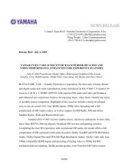
Figure 6 Logical channel spectral mapping -<br />
Service mode MA3.<br />
Figure 6 shows that service mode MA3 is the all<br />
digital equivalent <strong>of</strong> service mode MA1. Since<br />
there is no analog signal to serve as a backup<br />
channel, the time redundancy inherent in the P1<br />
logical channel serves this purpose.<br />
Lower <strong>Digital</strong><br />
Sideb<strong>and</strong>s<br />
Tertiary<br />
P3<br />
PIDS<br />
Primary<br />
Frequency (Hz) -9448<br />
-4906 -182 0 182<br />
Subcarrier Index -52<br />
-27<br />
-1 0 1<br />
P1<br />
AM Carrier<br />
Primary<br />
P2<br />
Upper <strong>Digital</strong><br />
Sideb<strong>and</strong>s<br />
4906<br />
Secondary<br />
PIDS<br />
P3<br />
9448<br />
27 52<br />
Figure 7 Logical channel spectral mapping -<br />
Service mode MA4.<br />
Figure 7 reveals that service mode MA4 is the all<br />
digital equivalent <strong>of</strong> service mode MA2. Again,<br />
since there is no analog signal to serve as<br />
backup, the time diverse P1 <strong>and</strong> P2 logical<br />
channels serve to backup each other. Also, to<br />
provide faster acquisition <strong>of</strong> digital audio, the P1<br />
logical channel uses a shorter interleaver.<br />
LAYER 1 FUNCTIONAL COMPONENTS<br />
This section describes the processing steps<br />
necessary to convert the various logical channels<br />
into an AM IBOC system waveform. Figure 8<br />
shows a functional block diagram <strong>of</strong> the Layer 1<br />
processing. <strong>The</strong> single underline notation for a<br />
logical channel name indicates that data is passed<br />
between the various functions as vectors. During<br />
the interleaving process, logical channels lose<br />
their identity as they are combined or split by the<br />
interleaving process.<br />
8