140 MHz SAW Filter 28 MHz Bandwidth Part Number - Spectrum ...
140 MHz SAW Filter 28 MHz Bandwidth Part Number - Spectrum ...
140 MHz SAW Filter 28 MHz Bandwidth Part Number - Spectrum ...

You also want an ePaper? Increase the reach of your titles
YUMPU automatically turns print PDFs into web optimized ePapers that Google loves.
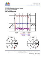
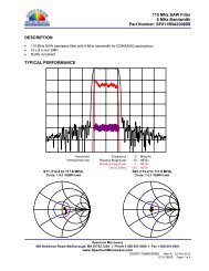
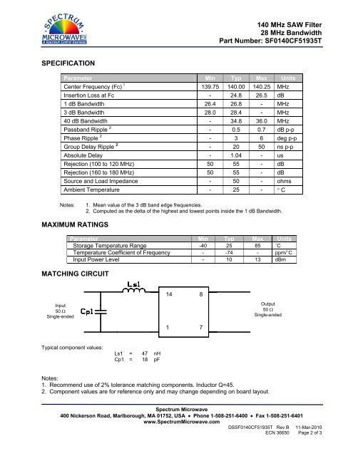
<strong>140</strong> <strong>MHz</strong> <strong>SAW</strong> <strong>Filter</strong><br />
<strong>28</strong> <strong>MHz</strong> <strong>Bandwidth</strong><br />
<strong>Part</strong> <strong>Number</strong>: SF0<strong>140</strong>CF51935T<br />
SPECIFICATION<br />
Parameter Min Typ Max Units<br />
Center Frequency (Fc) 1 139.75 <strong>140</strong>.00 <strong>140</strong>.25 <strong>MHz</strong><br />
Insertion Loss at Fc - 24.8 26.5 dB<br />
1 dB <strong>Bandwidth</strong> 26.4 26.8 - <strong>MHz</strong><br />
3 dB <strong>Bandwidth</strong> <strong>28</strong>.0 <strong>28</strong>.4 - <strong>MHz</strong><br />
40 dB <strong>Bandwidth</strong> - 34.8 36.0 <strong>MHz</strong><br />
Passband Ripple 2 - 0.5 0.7 dB p-p<br />
Phase Ripple 2 - 3 6 deg p-p<br />
Group Delay Ripple 2 - 20 50 ns p-p<br />
Absolute Delay - 1.04 - us<br />
Rejection (100 to 120 <strong>MHz</strong>) 50 55 - dB<br />
Rejection (160 to 180 <strong>MHz</strong>) 50 55 - dB<br />
Source and Load Impedance - 50 - ohms<br />
Ambient Temperature - 25 - ° C<br />
Notes:<br />
1. Mean value of the 3 dB band edge frequencies.<br />
2. Computed as the delta of the highest and lowest points inside the 1 dB <strong>Bandwidth</strong>.<br />
MAXIMUM RATINGS<br />
Parameter Min Typ Max Units<br />
Storage Temperature Range -40 25 85 ˚C<br />
Temperature Coefficient of Frequency - -74 - ppm/˚C<br />
Input Power Level - 10 13 dBm<br />
MATCHING CIRCUIT<br />
14 8<br />
Input<br />
50 Ω<br />
Single-ended<br />
Output<br />
50 Ω<br />
Single-ended<br />
1 7<br />
Typical component values:<br />
Ls1 = 47 nH<br />
Cp1 = 18 pF<br />
Notes:<br />
1. Recommend use of 2% tolerance matching components. Inductor Q=45.<br />
2. Component values are for reference only and may change depending on board layout.<br />
<strong>Spectrum</strong> Microwave<br />
400 Nickerson Road, Marlborough, MA 01752, USA • Phone 1-508-251-6400 • Fax 1-508-251-6401<br />
www.<strong>Spectrum</strong>Microwave.com<br />
DSSF0<strong>140</strong>CF51935T Rev B 11-Mar-2010<br />
ECN 36650 Page 2 of 3