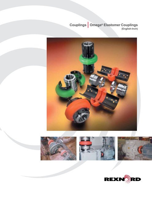
Couplings Omega® Elastomer Couplings
Couplings Omega® Elastomer Couplings
Couplings Omega® Elastomer Couplings

Create successful ePaper yourself
Turn your PDF publications into a flip-book with our unique Google optimized e-Paper software.
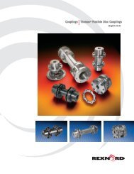
<strong>Couplings</strong><br />
Omega ® <strong>Elastomer</strong> <strong>Couplings</strong><br />
(English-Inch)
Omega ® <strong>Elastomer</strong>ic <strong>Couplings</strong><br />
OEM Performance and Coverage<br />
The unique split-in-half flex element and reversible hubs<br />
significantly reduce total costs by reducing inventory and<br />
assembly time.<br />
Rexnord Omega couplings are non-lubricated, material-flexing<br />
couplings utilizing a specially formulated polyurethane material<br />
engineered for maximum durabilty, strength and fatigue<br />
resistance.<br />
The Rex Omega HSU coupling (green) is specifically designed<br />
for hot and humid conditions.<br />
Rexnord is the leading coupling provider in the industry with a<br />
full-line of available solutions supported by trained customer<br />
service and application engineering professionals focused only<br />
on our coupling product line. For more information, contact<br />
your local Rexnord account executive.<br />
Features and Benefits<br />
• Split-in-half flex element<br />
design for simplified<br />
assembly and disassembly<br />
• Our selection software<br />
makes choosing the<br />
right coupling a snap<br />
Torsionally Soft<br />
Flex Element<br />
Radial Bolting<br />
Split-in-Half Design<br />
• Interchangeable hubs allow<br />
for reduced inventory<br />
• High misalignment capacity<br />
accommodates unavoidable<br />
misalignment with low<br />
reactionary forces<br />
• Torsionally soft flex<br />
element cushions shock<br />
loads and vibration<br />
extending equipment life<br />
• Polyurethane flex element<br />
does not require lubrication<br />
• Rexnord field specialists are<br />
locally based experts available<br />
to support key end-users<br />
• The Rexnord Omega<br />
HSU coupling (green) is<br />
specifically designed for hot<br />
and humid environments.<br />
In addition, the HSU material<br />
performs well in caustic<br />
and acidic environments.<br />
Consult Rexnord engineering<br />
for your application.<br />
Polyurethane-to-Metal Bond<br />
Interchangeable Hubs<br />
• Polyurethane-to-metal<br />
bond eliminates assembly<br />
and slippage problems<br />
associated with mechanically<br />
clamped designs<br />
Table Of Contents<br />
DESCRIPTION<br />
PAGE<br />
Installation and Misalignment Ratings 3<br />
Standard Close Coupled Design 4 – 5<br />
Spacer Design 6 – 7<br />
Spacing Options and Extended Spacer Design 8 – 9<br />
Mill Motor Design 10<br />
Special Designs 11<br />
Selection 12–14<br />
Bore Specifications and Finished Stock Bore Hubs 15<br />
Rexnord Omega couplings operate in<br />
either horizontal or vertical applications<br />
without any additional components.<br />
Ease of installation, ease of<br />
maintenance, and visual inspection<br />
make these couplings a must for<br />
many applications such as this mash<br />
cooker in a brewery.Never operate<br />
coupling without an OSHA approved guard.<br />
Ordering 16<br />
2
Installation<br />
Mount one hub to shaft, leave other<br />
hub loose for adjustment of spacing.<br />
Place half of the Rexnord ® Omega ®<br />
element around hubs and secure with<br />
self-locking capscrews. Omega<br />
element will space the other hub.<br />
Now secure the other hub.<br />
Mount other half of the Omega<br />
element. Tighten all capscrews to<br />
recommended torques below and<br />
you’re done! Refer to the installation<br />
instruction for further details.<br />
Severe static testing (5 × rating)<br />
shows element flexibility, rugged<br />
design and positive adhesive<br />
bond to the metal shoes.<br />
Angular<br />
4°<br />
3°<br />
2°<br />
1°<br />
0°<br />
Size 2-10<br />
Omega ® Coupling<br />
Allowable Misalignment<br />
Size 20-50<br />
OMEGA<br />
HUB<br />
Size 60-80<br />
Tested Tough<br />
Rigorous testing demonstrates that<br />
the Rexnord Omega coupling protects<br />
connected equipment from the damaging<br />
effects of misalignment, vibration and<br />
gross overload. Where other coupling<br />
designs might allow equipment<br />
damage, the super flexible element of<br />
Rexnord Omega couplings minimizes<br />
the reactionary forces on equipment<br />
bearings under severe misalignment<br />
conditions and reduces the effects<br />
of excessive shock overloads.<br />
Parallel<br />
OMEGA<br />
HUB<br />
OMEGA<br />
HUB<br />
Size 100-140<br />
Angular<br />
OMEGA<br />
HUB<br />
1/32 1/16 3/32 1/8 3/16<br />
Parallel<br />
Note:<br />
Any combination of parallel and angular misalignment which falls under the triangle<br />
will not cause a premature fatigue failure of the flexible element in normal use.<br />
Demonstrates coupling’s ability to<br />
accept severe misalignment.<br />
- Important-<br />
Recommended Capscrew Tourque<br />
For Proper Installation<br />
Coupling Torque - Dry<br />
Size In. Lbs. Ft. Lbs.<br />
2<br />
3<br />
4 204 17<br />
5<br />
10<br />
20<br />
30<br />
40<br />
360 30<br />
50<br />
60<br />
70 900 75<br />
80<br />
100<br />
120<br />
3240 270<br />
140 7080 590<br />
NOTE: Capscrews have self locking patches which<br />
should not be reused more than twice. Capscrews can<br />
be further used if a thread locking adhesive is applied.<br />
Do NOT Lubricate Capscrew Threads<br />
Important Note:<br />
Coupling alignment is directly related to<br />
smooth, efficient equipment operation. Care<br />
should be taken for best possible alignment.<br />
3
With Straight Bore Hubs<br />
B<br />
C B<br />
B C<br />
B<br />
Note: Hub/shoulder design<br />
varies per coupling<br />
size. Consult Rexnord<br />
for specific size<br />
assembly drawings.<br />
D<br />
(OUT) (OUT) (IN) (IN)<br />
A<br />
F<br />
(HUBS OUTBOARD)<br />
F<br />
(HUBS INBOARD)<br />
Recom.<br />
Dimensions In Inches<br />
Omega<br />
Continuous Continuous<br />
Max.<br />
Max.<br />
Weight<br />
Coupling<br />
HP/100 Torque<br />
C<br />
F<br />
Bore<br />
RPM A B<br />
D<br />
(Lb.)<br />
Size<br />
RPM (In. Lbs.)<br />
(In.) <br />
(In.) (Out) (In.) (Out)<br />
E2 1.13 0.30 190 7500 3.5 0.94 1.34 1.90 1.85 3.22 3.78 1.2<br />
E3 1.38 0.58 365 7500 4.00 1.50 0.81 1.31 2.32 3.81 4.31 2.4<br />
E4 1.63 0.88 550 7500 4.56 1.69 0.44 1.31 2.60 3.81 4.69 3.0<br />
E5 1.88 1.48 925 7500 5.38 1.75 0.81 1.81 3.13 4.31 5.31 5.4<br />
E10 2.13 2.30 1450 7500 6.38 1.88 0.56 1.81 3.65 4.31 5.56 8.2<br />
E20 2.38 3.65 2300 6600 7.25 2.06 0.50 2.38 4.48 4.62 6.50 13.0<br />
E30 2.88 5.79 3650 5800 8.25 2.31 0.56 2.44 5.42 5.19 7.06 21<br />
E40 3.38 8.85 5500 5000 9.50 2.50 0.56 2.68 6.63 5.56 7.68 35<br />
E50 3.63 12.14 7650 4200 11.00 2.75 0.63 3.38 8.13 6.13 8.88 54<br />
E60 4 19.84 12,500 3800 12.50 3.25 0.69 3.44 8.75 7.19 9.94 72<br />
E70 4.5 35.12 22,125 3600 14.00 3.62 0.75 3.75 9.25 8.00 11.00 86<br />
E80 6 62.7 39,500 2000 16.00 4.87 0.75 5.00 11.25 10.50 14.75 170<br />
E100 6.75 135 85,050 1900 21.00 5.50 1.75 3.75 14.13 12.75 14.75 244<br />
E120 7.5 270 170,100 1800 25.00 6.00 2.25 4.88 17.63 14.24 16.88 425<br />
E140 11 540 340,200 1500 30.00 7.00 3.00 5.00 20.88 17.00 19.00 746<br />
See page 14 for larger bore capacities with shallow keyways<br />
• Split-In-Half Flex Element<br />
Allows disassembly and replacement without<br />
disturbing hubs or connected equipment.<br />
• Reversible Hubs<br />
Accommodates different shaft spacing<br />
requirements, and allows compression bushings<br />
to be installed from either side of the hub.<br />
Straight Bore Hubs QD Hubs and Bushings TAPER-LOCK ® Hubs and Bushings<br />
4<br />
Note: Dimensions subject to change. Certified dimensions of ordered material furnished on request.
With Compression Bushed Hubs<br />
B<br />
F<br />
C<br />
B<br />
F<br />
C<br />
B<br />
(OUT)<br />
(IN)<br />
D<br />
A<br />
(OUT)<br />
(IN)<br />
D<br />
A<br />
NOTE: Bushings are NOT<br />
QD TAPER LOCK ®<br />
included with hubs<br />
(E3-E80 Dwg. Only)<br />
S p ecificatio n D ata With Q D H u b s<br />
D imensio ns In In ches<br />
O mega<br />
Recom. C o n tin uous C ontin uous<br />
<br />
C o uplin g QD Max. B ore H P /100 To rq u e Max.<br />
C<br />
F Weig h t<br />
S iz e B ush. No. (In.) R P M (In . Lbs.) R P M A B ( In.) ( O u t)<br />
D ( In. ) (O u t)<br />
(L b .)<br />
E 4 JA<br />
1.19<br />
. 88<br />
550<br />
7500<br />
4.56<br />
1.00<br />
1.22<br />
1.88<br />
2.60<br />
3.22<br />
3.88<br />
2. 1<br />
E 5 S H 1.63<br />
1.48<br />
925<br />
7500<br />
5.38<br />
1.25<br />
1.75<br />
1.88<br />
3.13<br />
4.25<br />
4.50<br />
3. 6<br />
E 10 S D S 1.94<br />
2.30<br />
1450<br />
7500<br />
6.38<br />
1.31<br />
1.19<br />
2.31<br />
3.65<br />
3.81<br />
4.94<br />
4. 8<br />
E 20 S K 2.50<br />
3.65<br />
2300<br />
6600<br />
7.25<br />
1.88<br />
0.62<br />
2.62<br />
4.48<br />
4.25<br />
6.38<br />
8. 5<br />
E 30 S F 2.94<br />
5.79<br />
3650<br />
5800<br />
8.25<br />
2.00<br />
1.44<br />
2.19<br />
5.42<br />
5.44<br />
6.19<br />
14. 0<br />
E 40 E 3.50<br />
8.85<br />
5500<br />
5000<br />
9.50<br />
2.63<br />
1.25<br />
1.75<br />
6.63<br />
6.50<br />
7.00<br />
23. 8<br />
E 50 E 3.50<br />
12.14<br />
7650<br />
4200<br />
11.00<br />
2.63<br />
1.37<br />
2.88<br />
8.13<br />
6.63<br />
8.13<br />
37. 6<br />
E 60 F 3.94<br />
19.84<br />
12,500<br />
3800<br />
12.50<br />
3.63<br />
1.50<br />
1.89<br />
8.75<br />
8.75<br />
9.13<br />
45. 5<br />
E 70 J 4.50<br />
35.12<br />
22,125<br />
3600<br />
14.00<br />
4.50<br />
1.31<br />
1.43<br />
9.25<br />
13.31<br />
10.43<br />
68. 1<br />
E 80 M 5.50<br />
62.70<br />
39,500<br />
2000<br />
16.00<br />
6.75<br />
0.75<br />
1.25<br />
11.25<br />
14.25<br />
14.75<br />
140<br />
E 100 M 5.50<br />
135<br />
85,050<br />
1900<br />
21.00<br />
6.80<br />
1.75<br />
1.16<br />
14.13<br />
15.34<br />
14.75<br />
250<br />
E 120 N 6.00<br />
270<br />
150,000<br />
1800<br />
25.00<br />
8.12<br />
1.74<br />
1.16<br />
17.63<br />
17.96<br />
16.88<br />
475<br />
E 140 P 7.00<br />
540<br />
250,000<br />
1500<br />
30.00<br />
9.36<br />
0.30<br />
3.00<br />
20.88<br />
19.00<br />
21.78<br />
782<br />
NO TE : D imensions may vary depending on bushing manufacturer.<br />
S p ecificatio n D ata With TA P E R -L O C K<br />
®<br />
H u b s<br />
O mega<br />
Recom. C o n tin uous C ontin uous<br />
D imensio ns In In ches<br />
<br />
C o uplin g<br />
S iz e<br />
TL<br />
B ush. No.<br />
Max. B ore<br />
(In.)<br />
H P /100<br />
R P M<br />
To rq u e<br />
(In . Lbs.)<br />
Max.<br />
R P M A B C D F<br />
Weig h t<br />
(L b .)<br />
E 3 1008<br />
1.00<br />
. 58<br />
365<br />
7500<br />
4.00<br />
. 88<br />
1.68<br />
2.32<br />
3.44<br />
1. 8<br />
E 4 1008<br />
1.00<br />
. 88<br />
550<br />
7500<br />
4.56<br />
. 88<br />
1.68<br />
2.60<br />
3.44<br />
2. 6<br />
E 5 1108<br />
1.13<br />
1.48<br />
925<br />
7500<br />
5.38<br />
. 88<br />
2.19<br />
3.13<br />
3.94<br />
4. 0<br />
E 10 1310<br />
1.44*<br />
2.30<br />
1450<br />
7500<br />
6.38<br />
1.00<br />
2.06<br />
3.65<br />
4.06<br />
6. 0<br />
E 20 1610<br />
1.69*<br />
3.65<br />
2300<br />
6600<br />
7.25<br />
1.00<br />
2.50<br />
4.48<br />
4.50<br />
9. 0<br />
E 30 2012<br />
2.12*<br />
5.79<br />
3650<br />
5800<br />
8.25<br />
1.25<br />
2.56<br />
5.42<br />
5.06<br />
13. 6<br />
E 40 2517<br />
2.69*<br />
8.85<br />
5500<br />
5000<br />
9.50<br />
1.75<br />
2.38<br />
6.63<br />
5.88<br />
21. 8<br />
E 50 2517<br />
2.69*<br />
12.14<br />
7650<br />
4200<br />
11.00<br />
1.75<br />
3.00<br />
8.13<br />
6.50<br />
31. 5<br />
E 60 3020<br />
3.25*<br />
19.84<br />
12,500<br />
3800<br />
12.50<br />
2.00<br />
3.31<br />
8.75<br />
7.31<br />
46. 6<br />
E 70 3535<br />
3.94<br />
35.12<br />
22,125<br />
3600<br />
14.00<br />
3.50<br />
2.38<br />
9.25<br />
9.38<br />
66. 7<br />
E 80 4040<br />
4.44<br />
62.70<br />
39,500<br />
2000<br />
16.00<br />
4.00<br />
3.75<br />
11.25<br />
11.75<br />
82<br />
( In.) ( O u t)<br />
( In. ) (O u t)<br />
E 100 4545<br />
4.94<br />
135<br />
85,050<br />
1900<br />
21.00<br />
4.50<br />
1.50<br />
6.00<br />
14.13<br />
10.50<br />
15.00<br />
250<br />
E 120 5050<br />
5.00<br />
270<br />
126,000<br />
1800<br />
25.00<br />
5.00<br />
2.00<br />
7.13<br />
17.63<br />
12.00<br />
17.13<br />
408<br />
E 140 7060<br />
7.00<br />
540<br />
340,200<br />
1500<br />
30.00<br />
6.00<br />
3.00<br />
7.00<br />
20.88<br />
15.00<br />
19.00<br />
660<br />
With shallow keyway.<br />
Service factor = 1.0. This rating may be lower is limited by the bushing rating, particularly if severe service conditions exist. C onsult bushing manufacturer.<br />
Without compression bushings.<br />
Inboard hub mounting (see drawing on page 4) requires bushing installation from coupling ends. A llow space (extra “B ” dimension) between<br />
coupling ends and equipment for bushing assembly/disassembly. Reverse taper hubs are available; consult Rexnord.<br />
A size 8065 bushing hub with 8.00" max bore is also available. C onsult Rexnord.<br />
Maximum bushing rating.<br />
*With steel bushings<br />
Note: Dimensions subject to change. Certified dimensions of ordered material furnished on request. 5
With Straight Bore Hubs<br />
B<br />
F<br />
C<br />
Note: Hub/shoulder design<br />
varies per coupling<br />
size. Consult Rexnord<br />
for specific size<br />
assembly drawings.<br />
D<br />
A<br />
S p ecificatio n D ata With S traig h t B o re H u b s<br />
<br />
D imensio n s In In ches<br />
O mega Recom. C o n tinuous C o n tinuous<br />
C o u p lin g Max. B ore H P /100 To rq u e Max.<br />
C<br />
F W eight<br />
S iz e (In.) R P M (In . L b s.) R P M A B ( In .) ( O u t)<br />
D ( In .)<br />
(O u t)<br />
(L b. )<br />
E S 2-R 1.13<br />
. 30<br />
190<br />
7500<br />
3.50<br />
. 94<br />
3.50<br />
4.00<br />
1.85<br />
5.75<br />
5.92<br />
2. 3<br />
E S 3-R 1.38<br />
. 58<br />
365<br />
7500<br />
4.00<br />
1.50<br />
3.50<br />
5.00<br />
2.32<br />
7.25<br />
8.00<br />
4. 0<br />
E S 4-R 1.63<br />
. 88<br />
550<br />
7500<br />
4.56<br />
1.69<br />
3.50<br />
5.00<br />
2.60<br />
7.25<br />
8.38<br />
5. 1<br />
E S 5-R 1.88<br />
1.48<br />
925<br />
7500<br />
5.38<br />
1.75<br />
3.50<br />
5.00<br />
3.13<br />
7.25<br />
8.50<br />
7. 5<br />
E S 10-R 2.13<br />
2.30<br />
1450<br />
7500<br />
6.38<br />
1.88<br />
3.50<br />
5.00<br />
3.65<br />
7.25<br />
8.75<br />
10. 3<br />
E S 20 2.38<br />
3.65<br />
2300<br />
4800<br />
7.25<br />
2.06<br />
2.55<br />
7.00<br />
4.48<br />
9.38<br />
11.12<br />
15. 6<br />
E S 30 2.88<br />
5.79<br />
3650<br />
4200<br />
8.25<br />
2.31<br />
2.05<br />
7.00<br />
5.42<br />
9.38<br />
11.62<br />
25. 1<br />
E S 40 3.38<br />
8.85<br />
5500<br />
3600<br />
9.50<br />
2.50<br />
1.67<br />
7.00<br />
6.63<br />
9.38<br />
12.00<br />
40<br />
E S 50 3.63<br />
12.14<br />
7650<br />
3100<br />
11.00<br />
2.75<br />
1.17<br />
7.00<br />
8.13<br />
9.38<br />
12.50<br />
60<br />
E S 60 4.00<br />
19.84<br />
12,500<br />
2800<br />
12.50<br />
3.25<br />
2.67<br />
9.75<br />
8.75<br />
12.50<br />
16.25<br />
84<br />
E S 70 4.50<br />
35.12<br />
22,125<br />
2600<br />
14.00<br />
3.62<br />
1.99<br />
9.75<br />
9.25<br />
12.50<br />
17.00<br />
102<br />
E S 80 6.00<br />
62.70<br />
39,500<br />
1800<br />
16.00<br />
4.87<br />
2.18<br />
9.75<br />
11.25<br />
12.50<br />
19.50<br />
180<br />
Suffix “R” designates high speed ring design. Rings are furnished standard for sizes E S2-R to E S10-R, optional for sizes E S20 to E S80.<br />
Service factor = 1.0.<br />
Spacer coupling furnished with optional high speed rings (sizes E S 20 to E S 80) can be operated up to maximum allowable speeds for standard<br />
series couplings. S ee RP M Ratings on page 4.<br />
Minimum shaft spacing is 0.25 inch. S ee page 8 for additional information.<br />
O verall length of element.<br />
With max bore hubs.<br />
See page 14 for larger bore capacities with shallow keyways.<br />
• Adjustable Spacer Design<br />
Optional hole mounting positions and reversible<br />
hub features allow adjustment to accommodate<br />
most shaft spacing requirements (see page 8)<br />
• Universal Hubs<br />
Straight bore and compression bushed hub<br />
designs are identical and interchangeable for both<br />
the spacer and standard couplings. This means<br />
maximum utilization of off the shelf inventory.<br />
Straight Bore Hubs QD Hubs and Bushings TAPER-LOCK ® Hubs and Bushings<br />
6<br />
Note: Dimensions subject to change. Certified dimensions of ordered material furnished on request.
With Compression Bushed Hubs<br />
B<br />
F<br />
C<br />
B<br />
F<br />
C<br />
(OUT)<br />
(IN)<br />
D<br />
A<br />
(OUT)<br />
(IN)<br />
D<br />
A<br />
Note: Bushings are NOT<br />
QD<br />
included with hubs<br />
TAPER LOCK ®<br />
S p ecificatio n D ata With Q D H u b s<br />
D imensio n s In In ches<br />
O mega<br />
Recom. C o ntin u o u s C o n tin u o us<br />
S p acer QD Max. B ore H P /100 To rq ue Max.<br />
C<br />
F W eig h t<br />
S iz e B ush. No. (In.) R P M (In . L bs.) R P M A B ( In .) ( O u t)<br />
D ( In .)<br />
(O u t)<br />
(L b .)<br />
E S 4-R JA<br />
1.19<br />
. 88<br />
550<br />
7500<br />
4.56<br />
1.00<br />
3.24<br />
5.56<br />
2.60<br />
7.25<br />
7.71<br />
4. 2<br />
E S 5-R S H 1.63<br />
1.48<br />
925<br />
7500<br />
5.38<br />
1.25<br />
3.51<br />
5.06<br />
3.13<br />
7.25<br />
7.82<br />
5. 7<br />
E S 10-R S D S 1.94<br />
2.30<br />
1450<br />
7500<br />
6.38<br />
1.31<br />
3.60<br />
5.49<br />
3.65<br />
7.25<br />
8.24<br />
6. 9<br />
E S 20 S K 2.50<br />
3.65<br />
2300<br />
4800<br />
7.25<br />
1.88<br />
2.82<br />
6.96<br />
4.48<br />
9.38<br />
10.84<br />
11. 1<br />
E S 30 S F 2.94<br />
5.79<br />
3650<br />
4200<br />
8.25<br />
2.00<br />
3.36<br />
6.44<br />
5.42<br />
9.38<br />
10.32<br />
17. 9<br />
E S 40 E 3.50<br />
8.85<br />
5500<br />
3600<br />
9.50<br />
2.63<br />
2.94<br />
5.74<br />
6.63<br />
9.38<br />
10.71<br />
28. 8<br />
E S 50 E 3.50<br />
12.14<br />
7650<br />
3100<br />
11.00<br />
2.63<br />
2.44<br />
6.24<br />
8.13<br />
9.38<br />
11.21<br />
43. 6<br />
E S 60 F 3.94<br />
19.84<br />
12,500<br />
2800<br />
12.50<br />
3.63<br />
4.25<br />
7.68<br />
8.75<br />
12.50<br />
14.65<br />
57. 4<br />
E S 70 J 4.50<br />
35.12<br />
22,125<br />
2600<br />
14.00<br />
4.50<br />
3.50<br />
6.72<br />
9.25<br />
12.52<br />
15.40<br />
84. 1<br />
E S 80 M 5.50<br />
62.70<br />
39,500<br />
1800<br />
16.00<br />
6.75<br />
1.35<br />
4.76<br />
11.25<br />
14.17<br />
17.58<br />
150. 0<br />
NO TE : D imensions may vary depending on bushing manufacturer.<br />
S p ecificatio n D ata With TA P E R -L O C K<br />
®<br />
H ub s<br />
D imensio n s In In ches<br />
O mega<br />
Recom. C o ntin u o u s C o n tin u o us<br />
S p acer TL Max. B ore H P /100 To rq ue Max.<br />
C<br />
F W eig h t<br />
S iz e B ush. No. (In.) R P M (In . L bs.) R P M A B ( In .) ( O u t)<br />
D ( In .)<br />
(O u t)<br />
(L b .)<br />
E S 3-R 1008<br />
1.00<br />
. 58<br />
365<br />
7500<br />
4.00<br />
. 88<br />
3.83<br />
5.38<br />
2.32<br />
7.25<br />
7.25<br />
3. 2<br />
E S 4-R 1008<br />
1.00<br />
. 88<br />
550<br />
7500<br />
4.56<br />
. 88<br />
3.83<br />
5.38<br />
2.60<br />
7.25<br />
7.25<br />
4. 2<br />
E S 5-R 1108<br />
1.13<br />
1.48<br />
925<br />
7500<br />
5.38<br />
. 88<br />
3.83<br />
5.38<br />
3.13<br />
7.25<br />
7.25<br />
6. 0<br />
E S 10-R 1310<br />
1.44*<br />
2.30<br />
1450<br />
7500<br />
6.38<br />
1.00<br />
3.71<br />
5.25<br />
3.65<br />
7.25<br />
7.25<br />
7. 9<br />
E S 20 1610<br />
1.69*<br />
3.65<br />
2300<br />
4800<br />
7.25<br />
1.00<br />
4.84<br />
6.75<br />
4.48<br />
9.38<br />
9.38<br />
11. 9<br />
E S 30 2012<br />
2.12*<br />
5.79<br />
3650<br />
4200<br />
8.25<br />
1.25<br />
4.59<br />
6.50<br />
5.42<br />
9.38<br />
9.38<br />
18. 0<br />
E S 40 2517<br />
2.69*<br />
8.85<br />
5500<br />
3600<br />
9.50<br />
1.75<br />
4.09<br />
6.00<br />
6.63<br />
9.38<br />
9.59<br />
26. 8<br />
E S 50 2517<br />
2.69*<br />
12.14<br />
7650<br />
3100<br />
11.00<br />
1.75<br />
4.09<br />
6.00<br />
8.13<br />
9.38<br />
9.59<br />
37. 4<br />
E S 60 3020<br />
3.25*<br />
19.84<br />
12,500<br />
2800<br />
12.50<br />
2.00<br />
6.09<br />
8.75<br />
8.75<br />
12.50<br />
12.84<br />
60. 7<br />
E S 70 3535<br />
3.94<br />
35.12<br />
22,125<br />
2600<br />
14.00<br />
3.50<br />
4.59<br />
7.34<br />
9.25<br />
12.50<br />
14.34<br />
81. 4<br />
E S 80 4040<br />
4.44<br />
62.70<br />
39,500<br />
1800<br />
16.00<br />
4.00<br />
4.09<br />
6.84<br />
11.25<br />
12.50<br />
14.84<br />
93. 2<br />
Suffix “R” designates high speed ring design. Rings are furnished standard for sizes E S2-R to E S10-R, optional for sizes E S20 to E S80.<br />
With shallow keyway.<br />
Service factor = 1.0. This rating is limited by the bushing rating.<br />
Spacer coupling furnished with optional high speed rings (sizes E S 20 to E S 80) can be operated up to maximum allowable speeds for standard<br />
series couplings.<br />
Minimum shaft spacing is 0.25 inch. S ee page 8 for additional information.<br />
Without compression bushings.<br />
* With steel bushings.<br />
Note: Dimensions subject to change. Certified dimensions of ordered material furnished on request. 7
“Adjustability”<br />
Shaft Spacing Possibilities<br />
(Using Straight Bore Hubs)<br />
The Rexnord ® Omega ® spacer coupling design (pages 6-7) provides clear space between hubs. There are no interfering center<br />
members or spools which allows shaft spacing as small as 1 /4”; however, for such small spacings, use of the standard Omega coupling<br />
would be recommended. The maximum shaft spacing for each coupling is shown of pages 6-7. Any ANSI, ISO or DIN spacing between<br />
1<br />
/4 inch and the maximum listed can be achieved without any additional parts. Hubs can be placed on the shafts as shown below.<br />
(OUT) (OUT) (OUT) (IN)<br />
Figure A<br />
Both hubs mounted outboard<br />
Figure B<br />
One hub mounted inboard<br />
One hub mounted outboard<br />
(IN)<br />
(IN)<br />
Figure C<br />
Both hubs mounted inward<br />
Use one half of the flex element to establish shaft spacing and appropriate mounting position. Optional hole mounting positions<br />
and reversible hubs allow adjustments as needed. Select the combination which most closely matches the dimensions<br />
desired between shafts (Figure D). Drawings with specific mounting positions/dimensions are available from Rexnord.<br />
Figure D<br />
Note: Optional capscrew hole mounting positions<br />
allow easy on-site adjustment to meet<br />
various shaft spacing requirements.<br />
Hubs can be flush with the shaft end (not shown), extended beyond the end of the shaft (Figure E) or recessed<br />
behind the shaft end provided there is sufficient keyway engagement (Figure F). Special sleeve extensions<br />
(see page 9) are available for spacing requirements in excess of those listed on pages 6-7.<br />
8<br />
Note: Shaft engagement should be equal to or<br />
greater than .8 times shaft diameter.<br />
100% shaft engagement is suggested for<br />
compression bushed hubs.<br />
Figure E<br />
Figure F
Extended Spacer Coupling<br />
Rexnord ® Omega ® extended spacer couplings are designed to connect equipment with shaft spacing requirements<br />
beyond the Omega spacer coupling capabilities. They are ideal for applications with wide non-standard shaft<br />
gaps, and can be an economic alternative to floating shaft couplings (i.e. stock pump applications).<br />
Sleeve extensions (“SE”) are furnished in steel. They mount to regular Omega spacer elements (standard<br />
elements for sizes E100 & E120) and cast iron or steel hubs – straight bore or compression bushed design.<br />
By adjusting the hub/shaft engagement (see figures E & F on page 8) and spacer element mounting position,<br />
the Omega extended spacer coupling can be utilized for many shaft spacing requirements.<br />
C<br />
C<br />
Single Extension<br />
Double Extension<br />
Maximu m S p acin g – “C ” D imensio n – In ches<br />
Max.<br />
With<br />
S H R B H u b s<br />
With<br />
H Q D H u bs<br />
With H TL H u bs<br />
O mega Max. R P M Max.<br />
Max.<br />
Max.<br />
Weight<br />
S p acer R P M Matched<br />
With o u t O n e Tw<br />
o With o u t O n e Tw<br />
o With o ut O n e Tw<br />
o (L b .)<br />
S iz e S tandard A ssemb ly S E S E S E S E S E S E S E S E S E O n e S E<br />
E S 3-R 1800<br />
3600<br />
5.00<br />
7.00<br />
9 .00<br />
— — — 5.38<br />
7.38<br />
9.38<br />
1. 2<br />
E S 4-R 1800<br />
3600<br />
5.00<br />
7.00<br />
9.00<br />
5.56<br />
7.56<br />
9.56<br />
5.38<br />
7.38<br />
9.38<br />
1. 4<br />
E S 5-R 1800<br />
3600<br />
5.00<br />
7.00<br />
9.00<br />
5.06<br />
7.06<br />
9.06<br />
5.38<br />
7.38<br />
9.38<br />
1. 5<br />
E S 10-R 1800<br />
3600<br />
5.00<br />
7.00<br />
9.00<br />
5.49<br />
7.49<br />
9.49<br />
5.25<br />
7.25<br />
9.25<br />
1. 6<br />
E S 20 1800<br />
3600<br />
7.00<br />
9.75<br />
12.50<br />
6.96<br />
9.71<br />
12.46<br />
6.75<br />
9.50<br />
12.25<br />
3. 7<br />
E S 30 1800<br />
3600<br />
7.00<br />
9.75<br />
12.50<br />
6.44<br />
8.97<br />
11.72<br />
6.50<br />
9.25<br />
12.00<br />
4. 5<br />
E S 40 1800<br />
3600<br />
7.00<br />
9.75<br />
12.50<br />
5.74<br />
8.23<br />
10.98<br />
6.00<br />
8.75<br />
11.50<br />
5. 3<br />
E S 50 1800<br />
3100<br />
7.00<br />
9.75<br />
12.50<br />
6.24<br />
8.73<br />
11.48<br />
6.00<br />
8.75<br />
11.50<br />
8. 0<br />
E S 60 1800<br />
2800<br />
9.75<br />
14.38<br />
19.00<br />
7.68<br />
12.31<br />
16.93<br />
8.75<br />
13.38<br />
18.00<br />
20. 8<br />
E S 70 1800<br />
2600<br />
9.75<br />
15.13<br />
20.50<br />
6.72<br />
12.10<br />
17.47<br />
7.34<br />
12.72<br />
18.09<br />
34. 6<br />
E S 80 1500<br />
1800<br />
9.75<br />
15.38<br />
21.00<br />
4.76<br />
10.39<br />
16.01<br />
6.84<br />
12.37<br />
18.00<br />
46. 2<br />
E 100 1500<br />
1800<br />
3.75<br />
8.75<br />
13.75<br />
1.75<br />
7.00<br />
12.25<br />
6.00<br />
11.25<br />
16.50<br />
76. 0<br />
E 120 1500<br />
1800<br />
4.88<br />
10.13<br />
15.38<br />
1.74<br />
6.74<br />
11.74<br />
7.13<br />
12.13<br />
17.13<br />
81. 3<br />
E 140 1200<br />
1500<br />
5.00<br />
10.50<br />
22.<br />
00 3.00 8.50 14.00 7.00 12.50 18.00 122.0<br />
Maximum spacings shown are with hubs mounted outboard and flush with shaft ends. Longer custom length extensions are available; consult Rexnord.<br />
Hub/sleeve extension assembly precisely machined and matched to obtain higher speed rating. Specify “Matched A ssembly” when ordering.<br />
Ordering Information: When ordering, be sure to specify whether one of two sleeve<br />
extensions are required. If custom length, specify distance between shaft ends.<br />
• Optional sleeve extensions (“SE”)<br />
An economical alternative to floating shaft couplings (i.e., stock pump applications).<br />
Sleeve Extensions<br />
Note: Dimensions subject to change. Certified dimensions of ordered material furnished on request. 9
Mill Motor <strong>Couplings</strong><br />
E<br />
H<br />
C<br />
B<br />
Note: Hub/shoulder design<br />
varies per coupling size.<br />
Consult Rexnord for specific<br />
size assembly drawings.<br />
G<br />
I<br />
D<br />
A<br />
C o u p lin g<br />
S iz e<br />
10<br />
20<br />
30<br />
40<br />
50<br />
60<br />
70<br />
80<br />
100<br />
120<br />
140<br />
S ervice<br />
F<br />
Mill Mo to r C o u p lin g D imensio n s<br />
Mill<br />
C omp lete<br />
D imensio n s<br />
Max.<br />
C o n tin uou s C o u p lin g<br />
Max.<br />
Moto<br />
r R P M H P /100 Weig ht,<br />
S traight<br />
S iz e<br />
R P M<br />
B o re<br />
(Lb.)<br />
A B C D E F G H I<br />
802A<br />
602<br />
7500<br />
2.<br />
3 15.<br />
6 6 3 /8 1 7 /8 1 9 / 32<br />
3 5 /8 3 6 5 / 32<br />
1 1 / 32<br />
3 3 / 16<br />
2 7 /8 2 1 /8<br />
802B<br />
6600<br />
3.65<br />
25.<br />
4 7 1 /4 2 1 / 16<br />
1 5 /8 4 1 3 6 / 16<br />
9<br />
/ 16<br />
802C<br />
/2<br />
4 1 /4 3 2 3 /8<br />
603<br />
3 1 /2 6 3 /8<br />
1 /2<br />
803<br />
804<br />
603<br />
5800<br />
5.79<br />
39.<br />
3 8 1 /4 2 5 / 16<br />
1 1 /2 5 7 / 16<br />
3 1 /2 7 5 / 16<br />
5 /8 4 9 / 16<br />
3 1 /2 2 7 /8<br />
604<br />
804<br />
604<br />
5000<br />
8.85<br />
58.<br />
0 9 1 /2 2 1 /2 1 1 /2 6 5 /8 3 1 /2 7 1 /2<br />
1 /2 4 7 /8 3 1 /2 3 3 /8<br />
406<br />
806<br />
606<br />
408<br />
608<br />
406<br />
806<br />
408<br />
608<br />
408<br />
808<br />
608<br />
410<br />
810<br />
610<br />
412<br />
612<br />
410<br />
810<br />
412<br />
812<br />
612<br />
14<br />
812<br />
614<br />
814<br />
616<br />
816<br />
618<br />
818<br />
818<br />
20<br />
622<br />
24<br />
F actor<br />
4200<br />
12.14<br />
83.<br />
5 11<br />
2 3 /4 1 3<br />
1 / 16<br />
8 1 /8<br />
3800<br />
19.84<br />
120.<br />
3 12<br />
1 /2 3 1 /4 1 3 /4 8 3 /4<br />
3600<br />
35.12<br />
150<br />
14<br />
3 5 /8 2 1 /2 9 1 /4<br />
2000<br />
62.<br />
7 235<br />
16<br />
4 7 /8 3 1 /8 1<br />
1 1 /4<br />
4 8 9 / 16<br />
4 1 /2 9 1 / 16<br />
1 1/ 16<br />
9 / 16<br />
4 9 5 /8<br />
4 1 /2 9 1 /2<br />
1 /2<br />
4 1 /2 10<br />
5 /8 1 1 /4<br />
5 1<br />
1 11<br />
/ 16<br />
1<br />
4 1 /2 12<br />
1 /2 1 3 /4<br />
5 13<br />
6 1 7 / 16<br />
1900<br />
135<br />
340<br />
21<br />
5 1 /2 3 3 /4 4<br />
1 1 /8<br />
5 14<br />
1 /4<br />
1 9 / 16<br />
2 1 /4<br />
2 1 /8<br />
5 1 /2 14<br />
3 /4 2<br />
5 1 /2 14<br />
3 /4 2 7 / 16<br />
1800<br />
270<br />
520<br />
25<br />
6 4 7 /8 17<br />
5 6 16<br />
7 /8 3 9 / 16<br />
/8<br />
6 6 16<br />
7 /8 3 1 /8<br />
1500<br />
540<br />
950<br />
30<br />
7 5 20<br />
7 7 19<br />
2 5 /8<br />
/8<br />
6 7 19<br />
2 5 /8<br />
- 1.0<br />
5 1 /2 4 3 5 /8<br />
6 5 / 16<br />
4 1 /2 4<br />
6 7 /8 4 3 /4 4 1 /2<br />
9 1 /4 6 6<br />
9 3 /4 10<br />
1 /4 6 3 /4<br />
11<br />
9 / 16<br />
11<br />
3 /4 7 1 /2<br />
13<br />
15<br />
9<br />
10<br />
Note: Dimensions subject to change. Certified dimensions of ordered material furnished on request.
Special Designs<br />
Rexnord ® Omega ® HSU Element<br />
Hydrolytically Stable Urethane for superior resistance to hot and<br />
humid conditions in addition to acidic and alkaline environments.<br />
The Omega HSU element in interchangeable with existing hubs.<br />
Stainless<br />
Steel<br />
Rexnord ® Omega ® Positive Drive<br />
Coupling<br />
With interlocking drive fail safe requirements.<br />
Rexnord ® Omega ® Stainless Steel<br />
Element<br />
Corrosion resistant 303/304 stainless steel shoes for severe<br />
environments.<br />
Stainless steel hubs also available.<br />
Rexnord ® Omega ® Keyless Hub/<br />
Bushing Design<br />
Several optional keyless Hub/Bushing designs are available<br />
for increased bore end shaft gap requirements.<br />
Rexnord ® Omega ® Spline Bore Hub<br />
1. Number of Teeth – Ex. 14T<br />
2. Pitch Fraction – Ex. 12/24 Pitch<br />
3. Pressure Angle – 30° P.A.<br />
4. Type of Tooth Shape – Ex. Involute or Straight Side<br />
5. Type of Root – Ex. Fillet or Flat Root<br />
6. Tolerance – Ex. Class I thru VII<br />
7. Type of Fit – Ex. Side Fit or Major Diameter Fit<br />
Rexnord ® Omega ® Light Duty Element<br />
Available in size E2LD only. Minimum O.D. (2.5”) for low<br />
profile applications. Max torque rating of 100 In. Lbs.<br />
Note: Dimensions subject to change. Certified dimensions of ordered material furnished on request. 11
Selection Procedures<br />
1. Determine HP/100RPM: HP/100 RPM = Horsepower x 100<br />
RPM<br />
2. Determine Service Factor:<br />
Select the proper Service Factor from Table on page<br />
13. If not listed, see Load Classification Table.<br />
Remember to consider both driver and driven<br />
equipment and temperature requirements.<br />
3. Multiply HP/100 by the service factor to get equivalent HP/100 RPM.<br />
4. Select the Coupling Size:<br />
From Table 1, with a rating equal to or greater than the<br />
equivalent HP/100 RPM determined in Step 3.<br />
5. Check Limiting Conditions:<br />
Be sure that the operating speed of the coupling does<br />
not exceed maximum RPM listed on page 4-7.<br />
6. Select Desired Hub Type:<br />
Select desired hub type and check maximum<br />
allowable coupling bore on page 14.<br />
OR<br />
1. Determine Operating Torque:<br />
( 63,000 x HP RPM )<br />
2. Multiply by Service Factor<br />
Select the proper Service Factor from Table on page 13.<br />
3. Select the Coupling Size:<br />
Select coupling size from Table 2 with a capacity<br />
equal to or greater than determined in Step 2.<br />
4. Follow Steps 5 & 6 Above<br />
Table 1<br />
Size<br />
Equivalent<br />
Standard Spacer HP/100 RPM<br />
E2 ES2 0.3<br />
E3 ES3 0.58<br />
E4 ES4 0.88<br />
E5 ES5 1.48<br />
E10 ES10 2.3<br />
E20 ES20 3.65<br />
E30 ES30 5.79<br />
E40 ES40 8.85<br />
E50 ES50 12.14<br />
E60 ES60 19.84<br />
E70 ES70 35.12<br />
E80 ES80 62.7<br />
E100 NA 135<br />
E120 NA 270<br />
E140 NA 540<br />
Table 2<br />
Torque Capacity<br />
Size<br />
Continuous<br />
Torque<br />
(In. Lbs.)<br />
Size<br />
Continuous<br />
Torque<br />
(In. Lbs.)<br />
2 190 40 5,500<br />
3 365 50 7,650<br />
4 550 60 12,500<br />
5 925 70 22,125<br />
10 1,450 80 39,500<br />
20 2,300 100 85,050<br />
30 3,650 120 170,100<br />
140 340,200<br />
Service Factors<br />
Service Factors are a means of classifying different equipment and applications into various load classifications.<br />
Due to variations in application of equipment, service factors are used to adjust equipment ratings to accommodate<br />
for variable loading conditions. This is a general guide. More specific factors are given on page 13.<br />
Load Classifications<br />
Service Factors<br />
Continuous service and running loads vary only slightly. 1.0<br />
Torque loading varies during operation of the equipment. 1.5<br />
Torque loading varies during operation, frequent stop/<br />
2.0<br />
start cycles are encountered.<br />
Omega ® Element<br />
Temperature Range (Ambient)<br />
-40°F<br />
+200°F<br />
to<br />
-40°C<br />
+93°C<br />
High Temperature<br />
Service Factor Adjustment*<br />
Ambient Temp. S.F. Adjust.<br />
+150°F (66°C) 0.025<br />
+165°F (74°C) 0.05<br />
+180°F (82°C) 0.75<br />
+200°F (93°C) 1<br />
*Added to application service factor<br />
For shock loading and substantial torque variations. 2.5<br />
For heavy shock loading or light reversing drives. 3.0<br />
Reversing torque loads do not necessarily mean reversal<br />
of rotation. Depending upon severity of torque reversal,<br />
Consult Rexnord<br />
such loads must be classified between “medium” and<br />
“extreme.”<br />
The service factor adjustment<br />
for high temperature is in<br />
addition to the service factor<br />
consideration for the driver and<br />
driven equipment. However, if<br />
high temperatures are typical for<br />
a specific application, maximum<br />
temperature consideration is<br />
incorporated into the “typical”<br />
service factor listing on page 13.<br />
i.e., steel mill runout tables.<br />
12
13<br />
Typical Service Factors – Motor And Turbine Driven Equipment <br />
AGITATORS<br />
Vertical and Horizontal Screw Propeller, Paddle . . . . . . . . . . . . . . . . . . . . . . . 1.5<br />
BLOWERS<br />
Centrifugal . . . . . . . . . . . . . . . . . . . . . . . . . . . . . . . . . . . . . . . . . . . . . . . . . . . . 1.0<br />
Lobe or Vane . . . . . . . . . . . . . . . . . . . . . . . . . . . . . . . . . . . . . . . . . . . . . . . . . . 1.5<br />
CAR DUMPER AND PULLER. . . . . . . . . . . . . . . . . . . . . . . . . . . . . . . . . . . . . . . 2.0<br />
COMPRESSORS<br />
Centrifugal . . . . . . . . . . . . . . . . . . . . . . . . . . . . . . . . . . . . . . . . . . . . . . . . . . . . 1.0<br />
Rotary, Lobe, or Vane . . . . . . . . . . . . . . . . . . . . . . . . . . . . . . . . . . . . . . . . . . . 2.0<br />
Rotary, Screw. . . . . . . . . . . . . . . . . . . . . . . . . . . . . . . . . . . . . . . . . . . . . . . . . 1.25<br />
Reciprocating . . . . . . . . . . . . . . . . . . . . . . . . . . . . . . . . . . . . . . . . . . . . . . . . . . . Á<br />
CONVEYORS<br />
Apron, Assembly, Belt, Chain, Flight, Oven . . . . . . . . . . . . . . . . . . . . . . . . . . . 1.5<br />
Reciprocating . . . . . . . . . . . . . . . . . . . . . . . . . . . . . . . . . . . . . . . . . . . . . . . . . . . <br />
Screw . . . . . . . . . . . . . . . . . . . . . . . . . . . . . . . . . . . . . . . . . . . . . . . . . . . . . . . 1.25<br />
CRANES AND HOISTS<br />
Main Hoist – Medium Duty . . . . . . . . . . . . . . . . . . . . . . . . . . . . . . . . . . . . . . . . 2.0<br />
Main Hoist – Heavy Duty . . . . . . . . . . . . . . . . . . . . . . . . . . . . . . . . . . . . . . . . . 2.5<br />
Skip Hoist . . . . . . . . . . . . . . . . . . . . . . . . . . . . . . . . . . . . . . . . . . . . . . . . . . . . . 2.0<br />
Bridge, Travel or Trolley . . . . . . . . . . . . . . . . . . . . . . . . . . . . . . . . . . . . . . . . . . 2.0<br />
DREDGES<br />
Cable Reel, Conveyor . . . . . . . . . . . . . . . . . . . . . . . . . . . . . . . . . . . . . . . . . . . 2.0<br />
Cutter Head Drive, Jig Drive . . . . . . . . . . . . . . . . . . . . . . . . . . . . . . . . . . . . . . . 3.0<br />
Pump, Screen, Drive, Stacker, Utility Winch. . . . . . . . . . . . . . . . . . . . . . . . . . . 2.0<br />
DYNAMOMETER . . . . . . . . . . . . . . . . . . . . . . . . . . . . . . . . . . . . . . . . . . . . . . . . 1.0<br />
ELEVATORS<br />
Bucket, Freight . . . . . . . . . . . . . . . . . . . . . . . . . . . . . . . . . . . . . . . . . . . . . . . . . 2.5<br />
EXCITER, GENERATOR . . . . . . . . . . . . . . . . . . . . . . . . . . . . . . . . . . . . . . . . . . 1.0<br />
EXTRUDER, PLASTIC . . . . . . . . . . . . . . . . . . . . . . . . . . . . . . . . . . . . . . . . . . . . 2.0<br />
FANS<br />
Centrifugal . . . . . . . . . . . . . . . . . . . . . . . . . . . . . . . . . . . . . . . . . . . . . . . . . . . . 1.0<br />
Cooling Tower . . . . . . . . . . . . . . . . . . . . . . . . . . . . . . . . . . . . . . . . . . . . . . . . . 2.0<br />
Forced Draft and Induced Draft . . . . . . . . . . . . . . . . . . . . . . . . . . . . . . . . . . . . 1.5<br />
Large Mine . . . . . . . . . . . . . . . . . . . . . . . . . . . . . . . . . . . . . . . . . . . . . . . . . . . . 2.0<br />
Propeller . . . . . . . . . . . . . . . . . . . . . . . . . . . . . . . . . . . . . . . . . . . . . . . . . . . . . . 1.5<br />
GENERATORS<br />
Even Load . . . . . . . . . . . . . . . . . . . . . . . . . . . . . . . . . . . . . . . . . . . . . . . . . . . . 1.0<br />
Hoist or Railway Service. . . . . . . . . . . . . . . . . . . . . . . . . . . . . . . . . . . . . . . . . . 2.0<br />
Welder Load . . . . . . . . . . . . . . . . . . . . . . . . . . . . . . . . . . . . . . . . . . . . . . . . . . . 2.5<br />
PRINTING PRESS. . . . . . . . . . . . . . . . . . . . . . . . . . . . . . . . . . . . . . . . . . . . . . . . 2.0<br />
PUMPS<br />
Centrifugal . . . . . . . . . . . . . . . . . . . . . . . . . . . . . . . . . . . . . . . . . . . . . . . . . . . . 1.0<br />
Positive Displacement . . . . . . . . . . . . . . . . . . . . . . . . . . . . . . . . . . . . . . . . . . . 1.5<br />
Rotary – Gear, Lobe, Vane. . . . . . . . . . . . . . . . . . . . . . . . . . . . . . . . . . . . . . . . 1.5<br />
Reciprocating . . . . . . . . . . . . . . . . . . . . . . . . . . . . . . . . . . . . . . . . . . . . . . . . . . . <br />
Progressive Cavity . . . . . . . . . . . . . . . . . . . . . . . . . . . . . . . . . . . . . . . . . . . . . 1.25<br />
Peristaltic . . . . . . . . . . . . . . . . . . . . . . . . . . . . . . . . . . . . . . . . . . . . . . . . . . . . . 1.5<br />
SCREENS<br />
Air Washing . . . . . . . . . . . . . . . . . . . . . . . . . . . . . . . . . . . . . . . . . . . . . . . . . . . 3.0<br />
Grizzly. . . . . . . . . . . . . . . . . . . . . . . . . . . . . . . . . . . . . . . . . . . . . . . . . . . . . . . . 1.0<br />
Coal and Sand (Rotary) . . . . . . . . . . . . . . . . . . . . . . . . . . . . . . . . . . . . . . . . . . 2.0<br />
Vibrating . . . . . . . . . . . . . . . . . . . . . . . . . . . . . . . . . . . . . . . . . . . . . . . . . . . . . . 5.0<br />
SEWAGE DISPOSAL EQUIPMENT . . . . . . . . . . . . . . . . . . . . . . . . . . . . . . . . . . 1.5<br />
STOKER . . . . . . . . . . . . . . . . . . . . . . . . . . . . . . . . . . . . . . . . . . . . . . . . . . . . . . . 1.5<br />
AGGREGATE PROCESSING, CEMENT<br />
Concrete Mixers . . . . . . . . . . . . . . . . . . . . . . . . . . . . . . . . . . . . . . . . . . . . . . . . 2.0<br />
Crushers, Ore or Stone. . . . . . . . . . . . . . . . . . . . . . . . . . . . . . . . . . . . . . . . . . . 3.0<br />
Dryer, Rotary . . . . . . . . . . . . . . . . . . . . . . . . . . . . . . . . . . . . . . . . . . . . . . . . . . 2.0<br />
Grizzly. . . . . . . . . . . . . . . . . . . . . . . . . . . . . . . . . . . . . . . . . . . . . . . . . . . . . . . . 3.0<br />
Hammermill . . . . . . . . . . . . . . . . . . . . . . . . . . . . . . . . . . . . . . . . . . . . . . . . . . . 2.5<br />
Mining Kilns . . . . . . . . . . . . . . . . . . . . . . . . . . . . . . . . . . . . . . . . . . . . . . . . . . . 2.5<br />
Tube, Rod and Ball Mills . . . . . . . . . . . . . . . . . . . . . . . . . . . . . . . . . . . . . . . . . . 2.5<br />
Tumbling Mill or Barrel . . . . . . . . . . . . . . . . . . . . . . . . . . . . . . . . . . . . . . . . . . . 2.0<br />
BREWERY AND DISTILLING<br />
Bottling and Can Filling Machinery, Brew Kettle, Cooker, Mash Tub . . . . . . . . 1.0<br />
Scale Hopper (frequent peaks). . . . . . . . . . . . . . . . . . . . . . . . . . . . . . . . . . . . . 2.0<br />
FOOD INDUSTRY<br />
Bottle and Can Filling . . . . . . . . . . . . . . . . . . . . . . . . . . . . . . . . . . . . . . . . . . . . 1.0<br />
Cereal Cooker . . . . . . . . . . . . . . . . . . . . . . . . . . . . . . . . . . . . . . . . . . . . . . . . . 1.0<br />
Dough Mixer, Meat Grinder . . . . . . . . . . . . . . . . . . . . . . . . . . . . . . . . . . . . . . . 2.0<br />
LUMBER INDUSTRY<br />
Band Resaw, Circular Resaw. . . . . . . . . . . . . . . . . . . . . . . . . . . . . . . . . . . . . . 2.0<br />
Edger, Head Rig, Hog, Log Haul. . . . . . . . . . . . . . . . . . . . . . . . . . . . . . . . . . . . 2.5<br />
Planer . . . . . . . . . . . . . . . . . . . . . . . . . . . . . . . . . . . . . . . . . . . . . . . . . . . . . . . . 2.0<br />
Rolls, Non-Reversing . . . . . . . . . . . . . . . . . . . . . . . . . . . . . . . . . . . . . . . . . . . . 2.0<br />
Rolls, Reversing . . . . . . . . . . . . . . . . . . . . . . . . . . . . . . . . . . . . . . . . . . . . . . . . 2.5<br />
Sawdust Conveyor . . . . . . . . . . . . . . . . . . . . . . . . . . . . . . . . . . . . . . . . . . . . . . 1.5<br />
Slab Conveyor, Sorting Table. . . . . . . . . . . . . . . . . . . . . . . . . . . . . . . . . . . . . . 2.0<br />
OIL INDUSTRY<br />
Chiller . . . . . . . . . . . . . . . . . . . . . . . . . . . . . . . . . . . . . . . . . . . . . . . . . . . . . . . . 1.0<br />
POWER INDUSTRY<br />
Ash Handling Conveyors . . . . . . . . . . . . . . . . . . . . . . . . . . . . . . . . . . . . . . . . . 1.5<br />
Baghouse Air Handling Fans . . . . . . . . . . . . . . . . . . . . . . . . . . . . . . . . . . . . . . 1.5<br />
Ball Mill . . . . . . . . . . . . . . . . . . . . . . . . . . . . . . . . . . . . . . . . . . . . . . . . . . . . . . . 2.5<br />
Belt Conveyors . . . . . . . . . . . . . . . . . . . . . . . . . . . . . . . . . . . . . . . . . . . . . . . . . 1.5<br />
Circulating pumps (centrifugal). . . . . . . . . . . . . . . . . . . . . . . . . . . . . . . . . . . . . 1.0<br />
Coal Grinders and Crushers. . . . . . . . . . . . . . . . . . . . . . . . . . . . . . . . . . . . . . . 2.5<br />
Coal Pulverizers and Hammermills . . . . . . . . . . . . . . . . . . . . . . . . . . . . . . . . . 2.5<br />
Cooling Tower Fans . . . . . . . . . . . . . . . . . . . . . . . . . . . . . . . . . . . . . . . . . . . . . 2.0<br />
FGD Slurry Pumps (centrifugal) . . . . . . . . . . . . . . . . . . . . . . . . . . . . . . . . . . . . 1.0<br />
Forced Draft Fan and Induced Draft Fan . . . . . . . . . . . . . . . . . . . . . . . . . . . . . 1.5<br />
Primary Air, Recycling Fans . . . . . . . . . . . . . . . . . . . . . . . . . . . . . . . . . . . . . . . 1.5<br />
Traveling Water Screens . . . . . . . . . . . . . . . . . . . . . . . . . . . . . . . . . . . . . . . . . 1.0<br />
PULP & PAPER MILLS<br />
Agitator . . . . . . . . . . . . . . . . . . . . . . . . . . . . . . . . . . . . . . . . . . . . . . . . . . . . . . . 1.5<br />
Barking Drum . . . . . . . . . . . . . . . . . . . . . . . . . . . . . . . . . . . . . . . . . . . . . . . . . . 3.0<br />
Beater and Pulper. . . . . . . . . . . . . . . . . . . . . . . . . . . . . . . . . . . . . . . . . . . . . . . 2.0<br />
Bleacher . . . . . . . . . . . . . . . . . . . . . . . . . . . . . . . . . . . . . . . . . . . . . . . . . . . . . . 1.0<br />
Calendar. . . . . . . . . . . . . . . . . . . . . . . . . . . . . . . . . . . . . . . . . . . . . . . . . . . . . . 2.5<br />
Chipper. . . . . . . . . . . . . . . . . . . . . . . . . . . . . . . . . . . . . . . . . . . . . . . . . . . . . . . 3.5<br />
Couch, Cylinder Dryer . . . . . . . . . . . . . . . . . . . . . . . . . . . . . . . . . . . . . . . . . . . 2.0<br />
Felt Stretcher . . . . . . . . . . . . . . . . . . . . . . . . . . . . . . . . . . . . . . . . . . . . . . . . . . 1.0<br />
Fourdrinier . . . . . . . . . . . . . . . . . . . . . . . . . . . . . . . . . . . . . . . . . . . . . . . . . . . . 2.0<br />
Jordan. . . . . . . . . . . . . . . . . . . . . . . . . . . . . . . . . . . . . . . . . . . . . . . . . . . . . . . . 2.5<br />
Press . . . . . . . . . . . . . . . . . . . . . . . . . . . . . . . . . . . . . . . . . . . . . . . . . . . . . . . . 2.5<br />
Pulp Grinder . . . . . . . . . . . . . . . . . . . . . . . . . . . . . . . . . . . . . . . . . . . . . . . . . . . 2.5<br />
Stock Chests . . . . . . . . . . . . . . . . . . . . . . . . . . . . . . . . . . . . . . . . . . . . . . . . . . 1.5<br />
Stock Pump<br />
Centrifugal . . . . . . . . . . . . . . . . . . . . . . . . . . . . . . . . . . . . . . . . . . . . . . . . . . . 1.0<br />
Reciprocating . . . . . . . . . . . . . . . . . . . . . . . . . . . . . . . . . . . . . . . . . . . . . . . . . 2.5<br />
Rotary. . . . . . . . . . . . . . . . . . . . . . . . . . . . . . . . . . . . . . . . . . . . . . . . . . . . . . . 2.0<br />
Suction Roll. . . . . . . . . . . . . . . . . . . . . . . . . . . . . . . . . . . . . . . . . . . . . . . . . . . . 2.5<br />
Winder . . . . . . . . . . . . . . . . . . . . . . . . . . . . . . . . . . . . . . . . . . . . . . . . . . . . . . . 2.0<br />
RUBBER INDUSTRY<br />
Banbury Mixer . . . . . . . . . . . . . . . . . . . . . . . . . . . . . . . . . . . . . . . . . . . . . . . . . 3.0<br />
Calendar. . . . . . . . . . . . . . . . . . . . . . . . . . . . . . . . . . . . . . . . . . . . . . . . . . . . . . 2.5<br />
Cracker, Mix Mill, Plasticator, Refiner, Sheeter, Tire Building Machine . . . . . . 2.0<br />
Tire and Tube Press Opener . . . . . . . . . . . . . . . . . . . . . . . . . . . . . . . . . . . . . . 1.0<br />
Tiber and Strainer. . . . . . . . . . . . . . . . . . . . . . . . . . . . . . . . . . . . . . . . . . . . . . . 2.0<br />
Warming Mill. . . . . . . . . . . . . . . . . . . . . . . . . . . . . . . . . . . . . . . . . . . . . . . . . . . 2.5<br />
Washer . . . . . . . . . . . . . . . . . . . . . . . . . . . . . . . . . . . . . . . . . . . . . . . . . . . . . . . 3.0<br />
STEEL INDUSTRY<br />
Coilers . . . . . . . . . . . . . . . . . . . . . . . . . . . . . . . . . . . . . . . . . . . . . . . . . . . . . . . 2.0<br />
Draw Benches . . . . . . . . . . . . . . . . . . . . . . . . . . . . . . . . . . . . . . . . . . . . . . . . . 2.0<br />
Edger Drives. . . . . . . . . . . . . . . . . . . . . . . . . . . . . . . . . . . . . . . . . . . . . . . . . . . 2.0<br />
Reel Drives . . . . . . . . . . . . . . . . . . . . . . . . . . . . . . . . . . . . . . . . . . . . . . . . . . . . 2.0<br />
Runout Tables (Non-Reversing). . . . . . . . . . . . . . . . . . . . . . . . . . . . . . . . . . . . 3.0<br />
Runout Tables (Reversing). . . . . . . . . . . . . . . . . . . . . . . . . . . . . . . . . . . . . . . . 4.5<br />
Soaking Pit Cover Drives . . . . . . . . . . . . . . . . . . . . . . . . . . . . . . . . . . . . . . . . . 3.0<br />
Tube Conveyor Rolls . . . . . . . . . . . . . . . . . . . . . . . . . . . . . . . . . . . . . . . . . . . . 2.5<br />
Wire Drawing . . . . . . . . . . . . . . . . . . . . . . . . . . . . . . . . . . . . . . . . . . . . . . . . . . 2.0<br />
TEXTILE MILLS<br />
Batcher, Calender, Card Machine, Dry Can . . . . . . . . . . . . . . . . . . . . . . . . . . . 2.0<br />
Dyeing Machinery. . . . . . . . . . . . . . . . . . . . . . . . . . . . . . . . . . . . . . . . . . . . . . . 1.0<br />
Loom. . . . . . . . . . . . . . . . . . . . . . . . . . . . . . . . . . . . . . . . . . . . . . . . . . . . . . . . . 2.0<br />
Mangle, Napper, Soaper . . . . . . . . . . . . . . . . . . . . . . . . . . . . . . . . . . . . . . . . . 1.5<br />
Spinner, Tenter Frame . . . . . . . . . . . . . . . . . . . . . . . . . . . . . . . . . . . . . . . . . . . 2.0<br />
Typical<br />
General Application<br />
Service Factor<br />
Typical<br />
Industry Application (cont’d)<br />
Service Factor<br />
The Service Factors listed are intended only as a general guide and for smooth<br />
power sources such as electric motors. For reciprocating prime movers, such as<br />
diesel or gas engines, add the following service factor:<br />
For 8 or more cylinders, add 0.5<br />
For 6 cylinders, add 1.0<br />
For 4 cylinders, add 1.5<br />
For less than 4 cylinders, consult Rexnord<br />
If both driver and driven equipment are reciprocating, consult Rexnord.<br />
Add 0.5 to service factor if drive is a hydraulic motor.<br />
Omega couplings are not recommended for turbine drives if the coupling cannot be<br />
protected from steam leakage or from speeds in excess of the coupling’s published<br />
speed rating (pages 4-7).<br />
Consult Rexnord Engineering<br />
IMPORTANT NOTE – The coupling selection criteria is intended for the<br />
determination of the coupling and style only. It is also recommended that the system<br />
be analyzed for torsional and lateral stability using the specific coupling mass-elastic<br />
data available from Rexnord. This analysis is the responsibility of the user since the<br />
coupling is only a single component in the system.<br />
CAUTION – In the drive systems sensitive to axial movement (i.e. sleeve bearing<br />
equipment), it may be necessary to limit axial force and/or displacement. Consult<br />
Rexnord for proper installation procedure.
Coupling Selection<br />
B o re R anges<br />
Straight<br />
B ore<br />
T APE R-LOCK<br />
®<br />
Q D<br />
H u b S iz e Min . B o re Max. B o re<br />
B ushin g<br />
N u mb er<br />
Min imu m<br />
B o re<br />
Maximu m<br />
B o re<br />
B u shin g<br />
N u mb er<br />
Minimu m<br />
B o re<br />
Maximu m<br />
B o re<br />
2 No<br />
Min.<br />
1 3 / 16<br />
NA<br />
NA<br />
3 3<br />
/8 1 3 /8 1008<br />
1<br />
/2 1 NA<br />
4 3<br />
/8 1 3 /4 1008<br />
1<br />
/2 1 JA<br />
3<br />
/8 1 3 /16<br />
5 3 /8 1 / 16<br />
1108<br />
1 /2 1 1 /8<br />
SH 1 /2 1 5 /8<br />
10<br />
3 /8 2 1 /4 1310<br />
1 /2 1 7 /16 S D S<br />
1 /2<br />
1 15 /16<br />
20<br />
3 /4 2 3 /4 1610<br />
1 /2 1 11 /16 S K<br />
1 /2 2 1 /2<br />
30<br />
3 /4 3 1 /4 2012<br />
1 /2 2 1 /8<br />
SF 1 /2 2 / 16<br />
40<br />
3 /4 3 3 /4 2517<br />
1 /2 2 11 /16<br />
E 7 /8 3 1 /2<br />
50<br />
1 1 /8 4 2517<br />
1 /2 2 11 /16<br />
E<br />
7 /8 3 1 /2<br />
60<br />
1 1 /8 4 1 /2 3020<br />
1 5/ 16<br />
3 1 /4<br />
F<br />
1 3 / 16<br />
70<br />
1 3 /8 4 7 /8 3535<br />
1 3 / 16<br />
3 15 /16<br />
J 1 7 / 16<br />
4 1 /2<br />
80<br />
1 7 /8 6 3 /4 4040<br />
1 7 / 16<br />
4 7 /16<br />
M<br />
1 / 16<br />
5 1 /2<br />
100<br />
1 7 /8 7 1 /4 4545<br />
1 / 16<br />
4 15 /16 M 1 / 16<br />
5 1 /2<br />
120<br />
1 7 /8 8 1 /4 5050<br />
2 5 / 16<br />
6 N 2 7 / 16<br />
6<br />
140<br />
1 7 /8 9 1 /4 7060<br />
4 9 / 16<br />
7 P 2 / 16<br />
7<br />
Bushings are not included with bushed hubs. Bushing bore ranges may vary, check with bushing manufacturer.<br />
Rough bores are slightly undersized to conform with minimum bore specifications.<br />
With shallow keyway and steel hub<br />
Rexnord Omega ® <strong>Couplings</strong> Interchange <br />
D o d g e L o vejo y TB Woods<br />
F alk G rid<br />
K o p -F lex<br />
O mega<br />
P ara-F lex (R u b ber) (Rubber) 1000T<br />
10T<br />
F<br />
G ear<br />
2 L-095<br />
5 1020T<br />
20T<br />
3 1H<br />
3 L-099,<br />
L-100<br />
6 1030T<br />
30T<br />
4 1H<br />
4 L-110<br />
7 1040T<br />
40T<br />
4 1H<br />
5 50<br />
L-110<br />
8 1040T,<br />
1050T<br />
40T,<br />
50T<br />
5,<br />
6<br />
1H,<br />
1<br />
/2H<br />
10<br />
60<br />
L-150,<br />
L-190<br />
9 1050T,<br />
1060T<br />
50T,<br />
60T<br />
7,<br />
8<br />
1 1 /2H<br />
20<br />
70<br />
L-225<br />
10<br />
1060T,<br />
1070T<br />
60T,<br />
70T<br />
8,<br />
9<br />
1 1 /2H,<br />
2H<br />
30<br />
80<br />
L-276<br />
11<br />
1070T,<br />
1080T<br />
70T,<br />
80T<br />
9,<br />
10<br />
2H,<br />
2<br />
/2H<br />
40<br />
90<br />
12<br />
1090T<br />
90T<br />
10<br />
2 1 /2H<br />
50<br />
110<br />
1090T<br />
90T<br />
11<br />
2 1 /2H<br />
60<br />
120<br />
13<br />
1090T<br />
90T<br />
11<br />
2 1 /2H<br />
70<br />
140<br />
14<br />
1100T<br />
100T<br />
13<br />
3H<br />
80<br />
160<br />
16<br />
1110T<br />
110T<br />
14<br />
3H<br />
100<br />
200<br />
NA<br />
1120T<br />
120T<br />
15<br />
120<br />
240<br />
NA<br />
1130T,<br />
1140T<br />
130T,<br />
140T<br />
16, 17<br />
140<br />
280<br />
NA<br />
1150T<br />
150T<br />
18<br />
C AUTION should be applied when using any interchange chart (particularly with respect to gear and grid couplings) since each product has different<br />
dimensions, benefits and service factor recommendations. This interchange is based on typical specifications for centrifugal pump applications at 1750<br />
RPM. F or specific applications, consult Rexnord, refer to page 12 ,or ask for our free Slide Selector. Use this chart as a general guide.<br />
C onsult Rexnord.<br />
14
Shaft<br />
Dia.<br />
Class 1<br />
Clearance Fit<br />
Interference<br />
Fit<br />
Shaft<br />
Dia.<br />
Class 1<br />
Clearance Fit<br />
Bore Specification<br />
<strong>Couplings</strong> will be bored in accordance with AGMA Standard 9002 for flexible couplings.<br />
Finished bore hubs will be Class 1 clearance fit unless otherwise specified.<br />
Interference<br />
Fit<br />
1/2 .500-.501 .4990-.4995 2 3/8 2.3750-2.3765 2.373-2.374<br />
5/8 .625-.626 .6240-.6245 2 1/2 2.5000-2.5015 2.498-2.499<br />
3/4 .750-.751 .7490-.7495 2 5/8 2.6250-2.6265 2.623-2.624<br />
7/8 .875-.876 .8740-.8745 2 3/4 2.7500-2.7515 2.748-2.749<br />
1 1.000-1.001 .9990-.9995 2 7/8 2.8750-2.8765 2.873-2.874<br />
1 1/8 1.125-1.126 1.1240-1.1245 3 3.0000-3.0015 2.998-2.999<br />
1 1/4 1.250-1.251 1.2490-1.2495 3 1/4 3.2500-3.2515 3.2470-3.2485<br />
1 3/8 1.375-1.376 1.3740-1.3745 3 1/2 3.5000-3.5015 3.4970-3.4985<br />
1 1/2 1.500-1.501 1.4990-1.4995 3 5/8 3.6250-3.6265 3.6220-3.6235<br />
1 5/8 1.625-1.626 1.623-1.624 3 3/4 3.7500-3.7515 3.7470-3.7485<br />
1 3/4 1.750-1.751 1.748-1.749 4 4.0000-4.0015 3.9970-3.9985<br />
1 7/8 1.875-1.876 1.873-1.874 4 1/2 4.500-4.502 4.4965-4.4980<br />
2 2.000-2.001 1.998-1.999 5 5.000-5.002 4.9965-4.9980<br />
2 1/8 2.1250-2.1265 2.123-2.124 5 1/2 5.500-5.502 5.4960-5.4975<br />
2 1/4 2.2500-2.2515 2.248-2.249 6 6.000-6.002 5.9960-5.9975<br />
B o re S iz es<br />
N o min al K eyw ay S etscrew<br />
S h aft<br />
D ia. C lass<br />
D iameter<br />
D epth<br />
Wid th<br />
2B N C<br />
O ver T h ru<br />
S q.<br />
R ect.<br />
Thread<br />
5 / 16<br />
7 / 16<br />
7<br />
/ 16<br />
9<br />
/ 16<br />
9<br />
/ 16<br />
7<br />
/8<br />
7 /8 1 1 /4<br />
Finished Stock Bore Hubs Available (listed by part number)<br />
(STRAIGHT BORE HUBS BORED IN ACCORDANCE WITH AGMA STANDARD 9002 CLASS 1 CLEARANCE FIT)<br />
Recommended<br />
Tightenin g<br />
To rq u e<br />
(In . L b s.)<br />
Size Bore 2 HSB 3 HSB 4 HSB 5 HSB 10 HSB 20 HSB 30 HSB 40 HSB 50 HSB 60 HSB<br />
5/8 7300218 7300242 7300272<br />
3/4 7300220 7300244 7300274 7300306<br />
7/8 7300225 7300245 7300275 7300308 7385821<br />
15/16 … … … 7300309<br />
1 7300230 7300250 7300280 7300310 7385820<br />
1-1/16 … … … 7300312<br />
1-1/8 7300235 7300255 7300285 7300315 7300345 7300649 7385825<br />
1-3/16 … … 7300286 7300318<br />
1-1/4 … 7300260 7300290 7300320 7300350 7300651 7385822<br />
1-5/16 … … … 7300322<br />
1-3/8 … 7300265 7300295 7300325 7300355 7300963 7385823<br />
1-7/16 … … 7300296 7300326 7300356<br />
1-1/2 … … 7300298 7300328 7300358 7300652 7300661 7300669<br />
1-5/8 … … 7300300 7300330 7300360 7300653 7369351 7369352<br />
1-11/16 … … … 7300332 7300361 7300656 7300964<br />
1-3/4 … … … 7300333 7300362 7300654 7300663 7300672 7300681<br />
1-7/8 … … … 7300335 7300365 7300655 7300662 7300671 7300684<br />
1-15/16 … … … … 7300366 7390410<br />
2 … … … … 7300368 7390411 7390413<br />
7390417<br />
2-1/8 … … … … 7300370 7300657 7300664 7300673 7300961 7390418<br />
2-3/16 … … … … … 7390412<br />
2-1/4 … … … … … 7300658 7300665 7300674 7300682<br />
2-3/8 … … … … … 7300659 7300666 7300675 7300962 7300691<br />
2-1/2 … … … … … … 7300667 7300676<br />
2-11/16 … … … … … … 7300965 7300678<br />
2-3/4 … … … … … … 7390414 7390415<br />
2-7/8 … … … … … … 7300668 7300677 7300683 7300692<br />
3-5/16 … … … … … … … … … 7300693<br />
3-3/8 … … … … … … … 7300679 7300686 7300694<br />
3 / 32<br />
1<br />
/8<br />
3<br />
/ 16<br />
1 /4<br />
5<br />
/ 16<br />
3 /8<br />
1 /2<br />
5 /8<br />
3 /4<br />
7 /8<br />
3 / 64<br />
–<br />
1<br />
/ 16<br />
3<br />
/ 64<br />
3<br />
/ 32<br />
1<br />
/ 16<br />
1 /8<br />
3 / 32<br />
5<br />
/ 32<br />
1<br />
/8<br />
3 / 16<br />
1 /8<br />
1 /4<br />
3 / 16<br />
5 / 16<br />
7 / 32<br />
3 /8<br />
1 /4<br />
7 / 16<br />
5 / 16<br />
3 /8<br />
5 /8<br />
7 / 16<br />
3 /4<br />
1 /2<br />
7 /8<br />
3 /4<br />
1<br />
/4-20<br />
87<br />
1 1 /4 1 3 /8<br />
3<br />
/8-16<br />
290<br />
1 3 /8 1 3 /4<br />
1 3 /4 2 1 /4<br />
1 /2-13<br />
620<br />
2 1 /4 2 3 /4<br />
5 /8-11<br />
1325<br />
2 3 /4 3 1 /4<br />
3 /4-10<br />
2400<br />
3 1 /4 3 3 /4<br />
7 /8-9<br />
5200<br />
3 3 /4 4 1 /2 1 1 /2<br />
4 1 /2 5 1 /2 1 1 /4<br />
5 1 /2 6 1 /2 1 1 /2<br />
1-8<br />
7200<br />
6 1 /2 7 1 /2 1 3 /4<br />
7 1 /2 9 2 1 3<br />
/4<br />
Maximum setscrew diameter is 1<br />
/4-20<br />
UNC for size #2 hub.<br />
Maximum setscrew size for hub sizes #3 thru #10 is<br />
/8-16 UNC .<br />
15
Ordering Instructions<br />
Standard and Spacer <strong>Couplings</strong><br />
When ordering a complete coupling, specify size/type of element and hubs (two hubs per complete coupling) options include:<br />
Element<br />
[E2 – E140] standard (close coupled)<br />
[ES2-R – ES80] spacer<br />
Hub<br />
1. Drawing of HUB showing complete<br />
bore and keyway details.<br />
— O R —<br />
2. Drawing of SHAFT with dimensions shown<br />
(LD) Large Diameter, Specify in Decimals.<br />
(S)<br />
(T)<br />
(P)<br />
[2HRB – 140HRB] straight hub-rough bore<br />
[2HSB – 60HSB] straight hub-stock bore (specify bore size from table on page 15)<br />
[2HCB – 140HCB] straight hub-custom bore (specify bore and keyway)<br />
[4HQD – 140HQD] hub-QD (bushing not included)<br />
[3HTL – 140HTL] hub-TAPER-LOCK ® (bushing not included)<br />
[10HMM – 140HMM] straight hub-mill motor (specify mill motor number, rough or custom bore)<br />
Order Example:<br />
Complete E50 standard (close coupled) coupling with one finished bore 2 1 /8” hub w/standard keyway and one QD hub less bushing.<br />
Order description:<br />
1 ea. E50 element<br />
1 ea. 50HSB – 2 1 /8” – std.<br />
1 ea. 50 HQD – steel<br />
W<br />
KEYWAY<br />
W<br />
N<br />
KEYWAY LD N<br />
W<br />
T<br />
KEYWAY<br />
N<br />
P<br />
LD N<br />
P<br />
E S<br />
E<br />
T<br />
N<br />
LD N<br />
P T<br />
P<br />
E S<br />
E<br />
P<br />
P<br />
below, allowing E SRexnord to bore hubs to suit. E<br />
Length of Taper, Measure parallel to Shaft centerline.<br />
Taper per Foot, Difference in Diameter in one foot length.<br />
Clearance space for drawing Hub up on tapered shaft.<br />
Usually 1 /8” or 1 /4”, depending on shaft size and taper.<br />
Keyway: Width, Depth.<br />
Note: Specify if keyway is parallel to Taper or if parallel to shaft<br />
center line.<br />
Specify depth at larger diameter of Taper if<br />
keyway is parallel to shaft center line.<br />
Tapered Bores<br />
With connected equipment in fixed position, the<br />
following additional information is necessary:<br />
Dimensions “V” and “X” must be given when one or both<br />
connected machines are fixed on their bases. Advise if<br />
AVAILABLE<br />
dimension “X” is LENGTH fixed, OF or if variable between what limits.<br />
SHAFT<br />
AVAILABLE<br />
LENGTH OF<br />
AVAILABLE SHAFT<br />
LENGTH OF<br />
C<br />
SHAFT<br />
V<br />
V<br />
X<br />
C<br />
C<br />
X<br />
V X<br />
A fixed “X” dimension may require altered or special coupling<br />
HUB hubs. COUNTERBORED Often the straight SHAFT bored PROJECTS hub can be HUB positioned SHORTENED on its shaft<br />
allowing the use of a standard coupling. See illustrations below.<br />
HUB COUNTERBORED SHAFT PROJECTS HUB SHORTENED<br />
HUB COUNTERBORED<br />
SHAFT PROJECTS<br />
Consult A.G.M.A. Standard 9002 “Taper Bores<br />
for Flexible <strong>Couplings</strong>” for new applications.<br />
HUB SHORTENED<br />
16
World Class Customer Service<br />
For more than 100 years, the dedicated people of Rexnord<br />
have delivered excellence in quality and service to our<br />
customers around the globe. Rexnord is a trusted<br />
name when it comes to providing skillfully engineered<br />
products that improve productivity and efficiency for<br />
industrial applications worldwide. We are committed<br />
to exceeding customer expectations in every<br />
area of our business: product design, application<br />
engineering, operations, and customer service.<br />
Because of our customer focus, we are able to<br />
thoroughly understand the needs of your business<br />
and have the resources available to work closely with<br />
you to reduce maintenance costs, eliminate redundant<br />
inventories and prevent equipment down time.<br />
Rexnord represents the most comprehensive portfolio<br />
of power transmission and conveying components<br />
in the world with the brands you know and trust.<br />
Omega and Rexnord are registered trademarks of Rexnord Industries, LLC. Falk is a trademark<br />
of Rexnord. Dodge, Paraflex, Lovejoy, TB Woods, and Kopflex are trademarks of their respective<br />
companies. Taper-Lock is a trademark of a bushing under license. All rights reserved.<br />
WORLDWIDE CUSTOMER SERVICE<br />
AUSTRALIA<br />
Rexnord Australia Pty. Ltd.<br />
Picton, New South Wales<br />
Phone: 61-2-4677-3811<br />
Fax: 61-2-4677-3812<br />
BRAZIL<br />
Rexnord Correntes Ltda.<br />
Sao Leopoldo - RS<br />
Phone: 55-51-579-8022<br />
Fax: 55-51-579-8029<br />
CANADA<br />
Rexnord Canada Ltd.<br />
Scarborough, Ontario<br />
Phone: 1-416-297-6868<br />
Fax: 1-416-297-6873<br />
CHINA<br />
Rexnord China<br />
Shanghai, China<br />
Phone: 86-21-62701942<br />
Fax: 86-21-62701943<br />
EUROPE<br />
Rexnord NV/SA<br />
Mechelen, Belgium<br />
Phone: 32-15-.443811<br />
Fax: 32-15-443860<br />
Rexnord Kette GmbH<br />
Betzdorf, Germany<br />
Phone: 49-2741-2840<br />
Fax: 49-2741-284-385<br />
LATIN AMERICA<br />
Rexnord International, Inc.<br />
Milwaukee, Wisconsin<br />
Phone: 1-414-643-2366<br />
Fax: 1-414-643-3222<br />
E-mail: international2@rexnord.com<br />
MEXICO<br />
Rexnord S.A. de C.V.<br />
Queretaro, Qro.<br />
Phone: 52-442-218.5000<br />
Fax: 52-.442-218-1090<br />
SINGAPORE<br />
Rexnord International, Inc.<br />
Singapore City, Singapore<br />
Phone: 65-6338-5622<br />
Fax: 65-6338-5422<br />
UNITED STATES<br />
Customer Service<br />
Phone: 1-866-REXNORD<br />
(1-866-739-6673)<br />
Fax: 1-614-675-1898<br />
E-mail: rexnordcs(state)@rexnord.com<br />
Example: rexnordcsohio@rexnord.com<br />
ALL COUNTRIES NOT LISTED<br />
Rexnord International<br />
Milwaukee, Wisconsin<br />
Phone: 1-414-643-2366<br />
Fax: 1-414-643-3222<br />
E-mail: international1@rexnord.com<br />
Rexnord Industries, LLC, Coupling Group, 5555 South Moorland Road, New Berlin WI 53151-7953 USA<br />
Phone: 262-796-4060 Fax: 262-796-4064<br />
4000 07/2009 Delzer Litho Printed in USA<br />
© 2009 Rexnord Industries LLC