Audio Codec with USB Interface, Mono ... - Texas Instruments
Audio Codec with USB Interface, Mono ... - Texas Instruments
Audio Codec with USB Interface, Mono ... - Texas Instruments

You also want an ePaper? Increase the reach of your titles
YUMPU automatically turns print PDFs into web optimized ePapers that Google loves.
PCM2912A<br />
SLES230–SEPTEMBER 2008.......................................................................................................................................................................................... www.ti.com<br />
Microphone Amplifier<br />
The PCM2912A has a low-noise, single-ended, mono microphone amplifier <strong>with</strong> a mute function that is controlled<br />
by MUTE (pin 30). The signal gain is selectable by MAMP (pin 23). The noise level at the input node is 5 μV RMS,<br />
and the input impedance is 20 kΩ.<br />
Input PGA<br />
The PCM2912A also has a low-noise input, programmable gain amplifier (PGA) for the microphone amplifier<br />
output/ADC input, <strong>with</strong> a gain range of +30 dB to –12 dB in 1dB/step.<br />
Sidetone Programmable Attenuator<br />
The PCM2912A has a low-noise, sidetone programmable attenuator <strong>with</strong> a mute function for the sidetone signal<br />
path (microphone amplifier output to output PGA input), and a gain range of 0 dB to –76 dB in 1 dB/step.<br />
Output Programmable Attenuator<br />
The PCM2912A has a low-noise output programmable attenuator <strong>with</strong> a mute function for mixed signal, which<br />
affects DAC output signal and sidetone signal. The output PGA gain range is 0 dB to –76 dB in 1 dB/step.<br />
V COM1 and V CCM2<br />
V COM2 (pin 12) is provided for the center voltage of the headphone amplifier. V COM1 (pin 11) is provided for the<br />
center voltage of all other analog circuits. Each V COM pin must be decoupled <strong>with</strong> an appropriate capacitor.<br />
Because the headphone output is disconnected when entering the suspend state, determining the capacitance is<br />
important to prevent pop noise, especially for V COM2 (pin 12). The equivalent resistance of V COM2 is 500 kΩ, and<br />
V COM1 is 15 kΩ.<br />
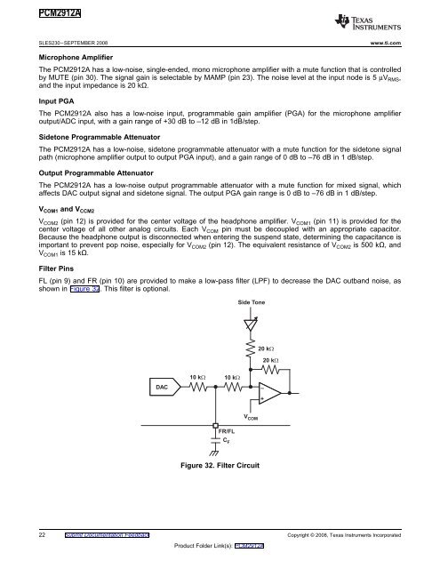
Filter Pins<br />
FL (pin 9) and FR (pin 10) are provided to make a low-pass filter (LPF) to decrease the DAC outband noise, as<br />
shown in Figure 32. This filter is optional.<br />
DAC<br />
10 k�<br />
10 k�<br />
FR/FL<br />
C F<br />
Side Tone<br />
V COM<br />
Figure 32. Filter Circuit<br />
22 Submit Documentation Feedback Copyright © 2008, <strong>Texas</strong> <strong>Instruments</strong> Incorporated<br />
Product Folder Link(s): PCM2912A<br />
20 k�<br />
–<br />
+<br />
20 k�