FOUNDRY TECHNOLOGY - Zollern
FOUNDRY TECHNOLOGY - Zollern
FOUNDRY TECHNOLOGY - Zollern

You also want an ePaper? Increase the reach of your titles
YUMPU automatically turns print PDFs into web optimized ePapers that Google loves.
4.2 Dimensional tolerance for wall thicknesses<br />
The wall thickness tolerance depend on<br />
• the size of the (ceramic) walls of the mould<br />
• their uninterrupted surface area<br />
• their possible thermal distortion<br />
• the metalostatic pressure of the molten metal.<br />
The wall thickness tolerance are, for this reason, not dependent<br />
on the level of accuracy. They are restricted (or reduced)<br />
by thicker edge sections, break-throughs (openings, holes),<br />
webs to be included in the casting, ribs and similar, which<br />
serve to ‘relieve’ the wall thickness. The tolerance range in<br />
question in each case is indicated in Table 2.<br />
Table 2: Wall thickness tolerances<br />
Smallest Material Material<br />
lateral length group D group A<br />
of a surface Fe, Ni, Co, Cu Al and Mg<br />
(Fig. 3) based on alloys based on alloys<br />
mm mm mm<br />
< 50 ± 0.25 ± 0.25<br />
50 up to 100 ± 0.30 ± 0.30<br />
100 up to 180 ± 0.40 ± 0.40<br />
180 up to 315 ± 0.50 ± 0.50<br />
> 315 ± 0.60 ± 0.60<br />
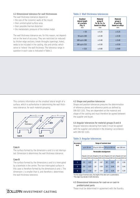
This contains information an the smallest lateral length of a<br />
surface, which is authoritative in determining the wall thickness<br />
tolerance, for each material grouping.<br />
a<br />
Wall<br />
thickness s<br />
b<br />
a<br />
c<br />
c<br />
b<br />
4.3 Shape and position tolerances<br />
Shape and position tolerances presume the determination<br />
of reference planes and reference points as defined by<br />
DIN ISO 1101. They are dependent on the material and<br />
shape of the casting and must therefore be agreed between<br />
the supplier and buyer.<br />
4.4 Angular tolerances for material groups D and A<br />
Angular tolerance deviating from table 3 must be agreed<br />
with the supplier and entered in the drawing I accordance<br />
with DIN ISO 1101.<br />
Case A<br />
Case B<br />
Table 3: Angular tolerances<br />
Case A<br />
The surface formed by the dimension a and b is not interrupted.<br />
Dimension b determines the wall thickness tolerance.<br />
Case B<br />
The surface formed by the dimensions a and b is interrupted<br />
by a borehole in the centre. The non-interrupted surface in<br />
this case is therefore formed by the dimensions b and c. The<br />
dimension c is smaller than b, and therefore c determines<br />
the wall thickness tolerance.<br />
Accurancy Range of nominal sizes 1<br />
level<br />
up to 30 mm 30 up to 100 mm 100 up to 200 mm over 200 mm<br />
Permissible misalignment<br />
Angular mm per Angular mm per Angular mm per Angular mm per<br />
minutes 100 mm minutes 100 mm minutes 100 mm minutes 100 mm<br />
1 30 2 0.87 30 2 0.87 30 2 0.87 20 2 0.58<br />
2 30 2 0.87 20 2 0.58 15 2 0.44 15 2 0.44<br />
3 20 2 0.58 15 2 0.44 10 2 0.29 10 2 0.29<br />
1<br />
For the range of nominal sizes, the length of the short arm is authoritative.<br />
2<br />
The angle may deviate in both directions.<br />
INVESTMENT CASTING<br />
4.5 Dimensional tolerances for cast-on or cast-in<br />
prefabricated parts<br />
These must be determined in agreement with the foundry.