innovative fe-analysis of the roller burnishing process for different ...
innovative fe-analysis of the roller burnishing process for different ...
innovative fe-analysis of the roller burnishing process for different ...

You also want an ePaper? Increase the reach of your titles
YUMPU automatically turns print PDFs into web optimized ePapers that Google loves.
F. Klocke, V. Bäcker, H. Wegner and A. Timmer.<br />
2 MODEL DEVELOPMENT<br />
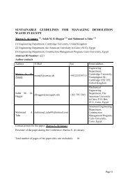
In <strong>the</strong> following sections <strong>the</strong> developed FE-models will be described (Figure 1).<br />
Figure 1: Modelling <strong>of</strong> <strong>the</strong> <strong>roller</strong> <strong>burnishing</strong> <strong>process</strong> <strong>for</strong> dif<strong>fe</strong>rent geometries<br />
The determination <strong>of</strong> an accurate stress distribution in <strong>the</strong> rime zone requires a high<br />
number <strong>of</strong> elements, which makes a simulation <strong>of</strong> <strong>the</strong> complete geometry impossible.<br />
There<strong>for</strong>e cut-out dimensions <strong>for</strong> each geometry were defined. This allows a robust and timeefficient<br />
<strong>roller</strong> <strong>burnishing</strong> simulation. In order to ensure a minimal influence <strong>of</strong> <strong>the</strong> boundaries<br />
on <strong>the</strong> stress development, symmetric boundary conditions were applied on <strong>the</strong>se surfaces.<br />
Each section was modelled as a de<strong>for</strong>mable 3D-body. The <strong>roller</strong> <strong>burnishing</strong> tools were<br />
simplified and modelled as rigid balls. This assumption is valid, because <strong>of</strong> <strong>the</strong> high hardness<br />
<strong>of</strong> <strong>the</strong> tungsten carbide <strong>roller</strong> ball (~2400 HV) compared to <strong>the</strong> <strong>process</strong>ed material (~450 HV).<br />
Contact between tool and workpiece was modelled using a finite-sliding <strong>for</strong>mulation where<br />
separation and sliding <strong>of</strong> finite amplitude, and arbitrary rotation <strong>of</strong> <strong>the</strong> surfaces may arise. The<br />
normal contact behaviour between <strong>the</strong> contact surfaces was modelled using <strong>the</strong> hard contact<br />
<strong>for</strong>mulation implemented in ABAQUS. The contact constraint is en<strong>for</strong>ced with a Lagrange<br />
multiplier representing <strong>the</strong> contact pressure in a mixed <strong>for</strong>mulation. The friction was modelled<br />
using an extended version <strong>of</strong> <strong>the</strong> classical isotropic Coulomb friction model. The extensions<br />
include an additional limit on <strong>the</strong> allowable shear stress, anisotropy, and <strong>the</strong> definition <strong>of</strong> a<br />
“secant” friction coefficient. Thereby, <strong>the</strong> friction model is able to consider stick-slip-ef<strong>fe</strong>cts,<br />
which can occur during <strong>roller</strong> <strong>burnishing</strong> at high pressures.<br />
The behaviour <strong>of</strong> <strong>the</strong> used materials, IN718 and Ti-6Al-4V, was modelled using <strong>the</strong><br />
implemented ABAQUS material models <strong>for</strong> metals subjected to cyclic loading. The elastic<br />
material behaviour was described using a linear elasticity model, whereas <strong>for</strong> <strong>the</strong> plastic<br />
behaviour a nonlinear, isotropic/kinematic hardening model was used. The model parameters<br />
<strong>for</strong> <strong>the</strong> description <strong>of</strong> <strong>the</strong> elastic material behaviour and <strong>for</strong> <strong>the</strong> plastic hardening were<br />
determined from material examinations and cyclic tests.<br />
2