- Page 1 and 2: RTD LIGHT RAIL DESIGN CRITERIA Regi
- Page 3 and 4: RTD Light Rail Design Criteria Manu
- Page 5 and 6: SECTION 1 - GENERAL INFORMATION 1.1
- Page 7 and 8: 1.3.0 PROCEDURES Design Engineers s
- Page 9 and 10: 30°F in the Denver metropolitan ar
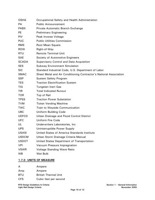
- Page 11 and 12: 1.6.0 ACRONYMS AND ABBREVIATIONS Th
- Page 13: FTA FWB GSA HPCU HSCB HVAC IBC ICEA
- Page 17 and 18: SECTION 2 - OPERATIONS PLAN 2.1.0 G
- Page 19 and 20: 2.2.0 MAINLINE The LRT is a convent
- Page 21 and 22: will occur later than the scheduled
- Page 23 and 24: SECTION 3 - CIVIL ENGINEERING 3.1.0
- Page 25 and 26: SECTION 3 - CIVIL ENGINEERING 3.1.0
- Page 27 and 28: 3.4.0 STREET DESIGN 3.4.1 General,
- Page 29 and 30: The purpose of drainage facilities
- Page 31 and 32: 3.5.3.1 Design Storms Facilities sh
- Page 33 and 34: a filter fabric (minimum weight 4 o
- Page 35 and 36: ends of direct-fixation bridges sha
- Page 37 and 38: 3.5.9 Easements All storm sewers cr
- Page 39 and 40: • Utilities located over the LRT
- Page 41 and 42: For mildly reinforced concrete stru
- Page 43 and 44: DESIGN CRITERIA TITLE: FIGURE: TYPI
- Page 45 and 46: 5.9’ 5.9’ 5.9’ 13.0’ C TRUC
- Page 47 and 48: SECTION 4 - TRACKWORK 4.1.0 GENERAL
- Page 49 and 50: SECTION 4 - TRACKWORK 4.1.0 GENERAL
- Page 51 and 52: The minimum length of tangent track
- Page 53 and 54: Where: Et = Total superelevation re
- Page 55 and 56: and must be rigorously monitored du
- Page 57 and 58: 4.3.0 VERTICAL TRACK ALIGNMENT 4.3.
- Page 59 and 60: L = 20(G1-G2) for V< 15 Where: L =
- Page 61 and 62: long tie. Geotextile fabric specifi
- Page 63 and 64: Other rail fastening methods shall
- Page 65 and 66:
Special drainage provisions shall b
- Page 67 and 68:
4.4.19 Track Bumping Posts Track bu
- Page 69 and 70:
4.5.11 Yard Lighting The yard is to
- Page 71 and 72:
DESIGN CRITERIA TITLE: TRACK CONSTR
- Page 73 and 74:
OUTER RAIL POINT A INNER RAIL INNER
- Page 75 and 76:
2500 2400 2200 ADDITIONAL WIDTH FOR
- Page 77 and 78:
CREST TYPE VERTICAL CURVES SAG TYPE
- Page 79 and 80:
DESIGN CRITERIA TITLE: DOUBLE TRACK
- Page 81 and 82:
2 23/32 " 1 1/4 " 1/16 "R GAUGE LIN
- Page 83 and 84:
115 RE RESILIENT RAIL CLIP (TYP.) W
- Page 85 and 86:
C RAIL L 10 1/2 " 7/8 " TYP. 7/8 "
- Page 87 and 88:
10’-8" 18" 16" 4’ 4’ 16" C&G
- Page 89 and 90:
SECTION 5 - STATION DESIGN CRITERIA
- Page 91 and 92:
5.1.1.2 Alignment 5.1.1.3 Architect
- Page 93 and 94:
5.2.0 SITE PLANNING transit user as
- Page 95 and 96:
• Identify the governing jurisdic
- Page 97 and 98:
5.3.2.1 Bus Access The bus system w
- Page 99 and 100:
5.3.1.4 Auto Access 5.3.3 Parking A
- Page 101 and 102:
5.5.0 TRANSITION PLAZA • Concentr
- Page 103 and 104:
5.6.2 Windscreens The following is
- Page 105 and 106:
5.6.6.5 Repair or Replacement 5.6.6
- Page 107 and 108:
5.7.2 Equipment Location All equipm
- Page 109 and 110:
5.9.2 Station Power and Electrical
- Page 111 and 112:
5.9.11 Pedestrian Accessways Lighti
- Page 113 and 114:
DESIGN CRITERIA TITLE: FIGURE: PLAT
- Page 115 and 116:
DESIGN CRITERIA TITLE: FIGURE: CENT
- Page 117 and 118:
DESIGN CRITERIA TITLE: FIGURE: CENT
- Page 119 and 120:
6.17.2 Live Load ..................
- Page 121 and 122:
6.3.3 Design Requirements Retaining
- Page 123 and 124:
Abutments, pier columns, and supers
- Page 125 and 126:
6.13.4 Components 6.13.4.1 Bridge a
- Page 127 and 128:
olts and the edge of the concrete p
- Page 129 and 130:
6.17.0 LOADS AND FORCES 6.17.1 Dead
- Page 131 and 132:
Detailed discussion of both vibrati
- Page 133 and 134:
For higher aerial structures, the v
- Page 135 and 136:
In addition, where the rail transit
- Page 137 and 138:
C L LRT ENVELOPE 14’ 7’-0" 7’
- Page 139 and 140:
STRAIGHT TRACK SECTION C L 7’-0"
- Page 141 and 142:
CURVED TRACK SECTION C L LRT ENVELO
- Page 143 and 144:
CLEARANCE ENVELOPE 14’ 45^ 45^ 10
- Page 145 and 146:
7.1.0 GENERAL SECTION 7 - COMMUNICA
- Page 147 and 148:
with the several parties with whom
- Page 149 and 150:
7.4.3 System Requirements 7.4.3.1 R
- Page 151 and 152:
• Have sufficient redundant equip
- Page 153 and 154:
7.5.0 COMMUNICATIONS 7.5.1 Radio Sy
- Page 155 and 156:
OCC. The CTS includes fiber optic c
- Page 157 and 158:
7.6.2 SCADA Remote I/O Equipment Re
- Page 159 and 160:
SECTION 8 -SIGNAL SYSTEM 8.1.0 GENE
- Page 161 and 162:
SECTION 8 -SIGNAL SYSTEM 8.1.0 GENE
- Page 163 and 164:
A TWC system, compatible with the L
- Page 165 and 166:
8.8.0 HEADWAYS & BLOCK LAYOUT The d
- Page 167 and 168:
TABLE 8A - FUNDAMENTAL ASPECTS OF C
- Page 169 and 170:
8.14.0 MAINLINE TRACK SWITCHES 8.14
- Page 171 and 172:
• Application Software shall be s
- Page 173 and 174:
the phase-selective, two-element ty
- Page 175 and 176:
() *+ () (,(+ () - .
- Page 177 and 178:
. ! ' '#3- #"#!$ !9-.$! #*// 3! '!#
- Page 179 and 180:
&/%/7 $+ 8 $$-$ 5 '! !## ')!
- Page 181 and 182:
• '-'$!##'!## • '-#66! • 66!
- Page 183 and 184:
• // • '-# *E:.!/F!/'6 * !!$.!-
- Page 185 and 186:
*! #"#!$ *! #!!# ' *! "'# #*// 3!
- Page 187 and 188:
&/&/ @ *!.6.*#*//4#$*/"-'!*! !//
- Page 189 and 190:
'/" + + + ) //'!#6 4'$!/#!/!#*/
- Page 191 and 192:
*!#5$!@!5!#*//3!'!#6!'#**!$
- Page 193 and 194:
#"#!$ //!/!/!5!#8/-'6!/"68)!''8#*//
- Page 195 and 196:
$./#*!' 3" $.!'! 3' !! . !# !* #-3
- Page 197 and 198:
#/!/> + ( ! #*// 3! ( 4$/ #/'8
- Page 199:
7/" ( $+ + . +
- Page 202 and 203:
• //!/'!% & • //!/5!"'!% @&
- Page 204 and 205:
*!! 3#/!# #-* # -'!6-' -/!# 5-'# !
- Page 206 and 207:
5 !9-!' 3!-#! 5 !/!$6! !5!!! % & *6
- Page 208 and 209:
() ,,(0 7 !""#
- Page 210 and 211:
SECTION 10 - STRAY CURRENT/CORROSIO
- Page 212 and 213:
Soil/rock samples should be obtaine
- Page 214 and 215:
• Mechanical characteristics capa
- Page 216 and 217:
Impressed current rectifier systems
- Page 218 and 219:
TABLE 10-A- ACCEPTABLE CEMENT TYPE
- Page 220 and 221:
Reinforced concrete piling, includi
- Page 222 and 223:
normal operating conditions, rather
- Page 224 and 225:
10.3.1.3 Mainline Negative Return S
- Page 226 and 227:
Other electrically grounded track,
- Page 228 and 229:
washers for anchor bolts and dielec
- Page 230 and 231:
ars installed on each side of a bre
- Page 232 and 233:
• Provide a waterproofing, electr
- Page 234 and 235:
o Thermite weld or braze the cable
- Page 236 and 237:
• The requirement for electrical
- Page 238 and 239:
• Commercial blast surface accord
- Page 240 and 241:
10.5.4 Track-to-Earth Resistance Te
- Page 242 and 243:
SECTION 12 - FARE COLLECTION EQUIPM
- Page 244 and 245:
• Include complete on-line TVM ne
- Page 246 and 247:
ase which shall accommodate the sta
- Page 248 and 249:
While the central data system will
- Page 250 and 251:
The abilities to place an individua
- Page 252 and 253:
13.9.0 ELECTRICAL .................
- Page 254 and 255:
The predominant seating arrangement
- Page 256 and 257:
13.2.1.2 Pantograph Dimensions TABL
- Page 258 and 259:
13.2.5 Catenary Voltages The vehicl
- Page 260 and 261:
Minimum safe operating speed: 105 k
- Page 262 and 263:
13.2.10.2 Conductive Emission Limit
- Page 264 and 265:
Individual car systems will meet th
- Page 266 and 267:
13.3.4 Windows 13.4.0 COUPLER The w
- Page 268 and 269:
The vehicle will provide 3-phase 20
- Page 270 and 271:
Radios will be commercial units fun
- Page 272 and 273:
associated with the active cab of a
- Page 274 and 275:
TABLE OF CONTENTS SECTION 14 - SYST
- Page 276 and 277:
minimized. Software controlled or m
- Page 278 and 279:
no provisions have been made to pro
- Page 280 and 281:
• System designs that positively
- Page 282 and 283:
Train Signals Communications - Cent
- Page 284 and 285:
table describes ROW conditions and
- Page 286 and 287:
14.8.0 EMERGENCY ACCESS/EGRESS, STA
- Page 288 and 289:
• Channeling or other barriers re
- Page 290 and 291:
security room shall have a conduit
- Page 292 and 293:
to +60˚C. All emergency telephone
- Page 294 and 295:
Rail Track/Track Structure/Signals
- Page 296 and 297:
• Add safety or security devices
- Page 298:
The design shall protect the facili