Dual Abutment
Dual Abutment
Dual Abutment
Create successful ePaper yourself
Turn your PDF publications into a flip-book with our unique Google optimized e-Paper software.
SuperLine & Implantium Surgical / Prosthesis Manual SISP-1104 [Rev.1]<br />
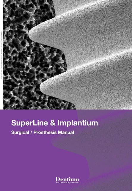
SuperLine & Implantium<br />
Surgical / Prosthesis Manual
SURGICAL MANUAL<br />
Surgical Drill Sequence 04<br />
Drilling Depth Guide 06<br />
Fixture Connection 08<br />
Installation Procedure & Warnings 09<br />
Surgical Kit Maintenance 10
04<br />
SuperLine & Implantium Surgical / Prosthesis Manual<br />
Surgical Drill Sequence<br />
8 10 12 14 16<br />
Drilling Sequence Guide<br />
Lindemann<br />
guide<br />
drill<br />
Lindemann<br />
first<br />
drill<br />
3.6 4.0 4.5<br />
5.0<br />
Final drill<br />
Countersink<br />
3.6<br />
4.0<br />
4.5 5.0 6.0 7.0 7.0<br />
Ø2.2 Ø2.6<br />
Ø2.85 Ø3.3 Ø3.85 Ø4.4<br />
Platform: Ø3.6<br />
Body: Ø3.4<br />
Ø3.6 Ø4.0 Ø4.5 Ø5.0 Ø6.0 Ø5.4 Ø7.0<br />
Platform: Ø4.0<br />
Body: Ø3.8<br />
Platform: Ø4.5<br />
Body: Ø4.3<br />
Platform: Ø5.0<br />
Body: Ø4.8<br />
Platform: Ø6.0<br />
Body: Ø4.8<br />
Platform: Ø7.0<br />
Body: Ø5.8
SuperLine & Implantium Surgical / Prosthesis Manual 05<br />
During fixture insertion, 30~45N•cm torque at 20rpm is recommended.<br />
• Countersink drill is used in cases with dense cortical bone.<br />
• If the bone density is D1~D3, it is recommended to countesink after final drill.<br />
• During insertion, if the 4.8 fixture is not tight enough, replace it with a 4.8W fixture which has wider neck.<br />
• The countersink drill’s actual diameter is 0.1mm larger than the fixture platform.<br />
Determination of Fixture Top Level<br />
+0.5mm<br />
-0.5mm<br />
Length 7mm<br />
Crestal<br />
Bone<br />
Top level of fixture needs to be located 0.5mm<br />
below the marginal crestal bone level to minimize<br />
bone loss after implantation. However, only for the<br />
fixture of 7mm length, top level of fixture should be<br />
located 0.5mm above the marginal crestal bone<br />
level.<br />
7mm<br />
10mm<br />
Depth Indication<br />
Depth<br />
Gauge<br />
• Use the Depth Gauge after first drill / Lindemann first drill to check depth of drilling<br />
• Place the Depth gauge against the wall of the osteotomy
06<br />
SuperLine & Implantium Surgical / Prosthesis Manual<br />
Drilling Depth Guide<br />
D1~D2<br />
( I )<br />
( II )<br />
D3~D4<br />
Countersink Depth Guide<br />
• Drilling depth of the countersink depends on the patient’s bone quality.<br />
• If the bone density is D1~D2, it is recommended to drill up to the top line ( I )<br />
of laser mark on the countersink.<br />
• If the bone density is D3~D4, it is recommended to drill up to the bottom line<br />
( II ) of laser mark on the countersink.<br />
Platform: Ø3.6 / Body: Ø3.4<br />
(1000rpm/30~45N·cm)<br />
Lindemann<br />
guide<br />
drill<br />
Lindemann<br />
first<br />
drill<br />
Final drill<br />
Ø3.6<br />
Countersink<br />
Ø3.6<br />
FX 3610 SW<br />
Ø3.6<br />
FX 3410<br />
Ø3.6<br />
0.5mm<br />
10mm<br />
Ø3.4<br />
Ø3.4<br />
Platform: Ø4.0 / Body: Ø3.8<br />
(1000rpm/30~45N·cm)<br />
Lindemann<br />
guide<br />
drill<br />
Lindemann<br />
first<br />
drill<br />
Final drill<br />
Ø3.6<br />
Final drill<br />
Ø4.0<br />
Countersink<br />
Ø4.0<br />
FX 4010 SW<br />
Ø4.0<br />
FX 3810<br />
Ø4.0<br />
0.5mm<br />
10mm<br />
Ø3.8<br />
Ø3.8<br />
Platform: Ø4.5 / Body: Ø4.3<br />
(1000rpm/30~45N·cm)<br />
Lindemann<br />
guide<br />
drill<br />
Lindemann<br />
first<br />
drill<br />
Final drill<br />
Ø3.6<br />
Final drill<br />
Ø4.0<br />
Final drill<br />
Ø4.5<br />
Countersink<br />
Ø4.5<br />
FX 4510 SW<br />
Ø4.5<br />
FX 4310<br />
Ø4.5<br />
0.5mm<br />
10mm<br />
Ø4.3<br />
Ø4.3
SuperLine & Implantium Surgical / Prosthesis Manual 07<br />
Platform: Ø5.0 / Body: Ø4.8<br />
(1000rpm/30~45N·cm)<br />
Lindemann<br />
guide<br />
drill<br />
Lindemann<br />
first<br />
drill<br />
Final drill<br />
Ø3.6<br />
Final drill<br />
Ø4.0<br />
Final drill<br />
Ø4.5<br />
Final drill<br />
Ø5.0<br />
Countersink<br />
Ø5.0<br />
FX 5010 SW<br />
Ø5.0<br />
FX 4810<br />
Ø5.0<br />
0.5mm<br />
10mm<br />
Ø4.8<br />
Ø4.8<br />
Platform: Ø6.0 / Body: Ø4.8<br />
(1000rpm/30~45N·cm)<br />
Lindemann<br />
guide<br />
drill<br />
Lindemann<br />
first<br />
drill<br />
Final drill<br />
Ø3.6<br />
Final drill<br />
Ø4.0<br />
Final drill<br />
Ø4.5<br />
Final drill<br />
Ø5.0<br />
Countersink<br />
Ø6.0<br />
FX 6010 SW<br />
Ø6.0<br />
0.5mm<br />
10mm<br />
Ø4.8<br />
Platform: Ø7.0 / Body: Ø5.8<br />
(1000rpm/30~45N·cm)<br />
Lindemann<br />
guide<br />
drill<br />
Lindemann<br />
first<br />
drill<br />
Final drill<br />
Ø3.6<br />
Final drill<br />
Ø4.0<br />
Final drill<br />
Ø4.5<br />
Final drill<br />
Ø5.0<br />
Countersink<br />
Ø6.0<br />
Final drill<br />
Ø7.0<br />
Countersink<br />
Ø7.0<br />
FX 7010 SW<br />
Ø7.0<br />
0.5mm<br />
10mm<br />
Ø5.8
08<br />
SuperLine & Implantium Surgical / Prosthesis Manual<br />
Fixture Connection<br />
Caution_ When opening the fixture pack,<br />
hold the fixture container upward<br />
and engage the adapter into the<br />
fixture.<br />
By handpiece<br />
20rpm/35N·cm<br />
By ratchet<br />
Directions Using the Hand-piece / Ratchet Adapter<br />
Connection<br />
Hand-piece<br />
adapter<br />
Ratchet<br />
adapter<br />
The rachet adapter and the fixture interal hex must be<br />
connected firmly together.
SuperLine & Implantium Surgical / Prosthesis Manual 09<br />
Installation Procedure & Warnings<br />
Cover Screw<br />
<br />
By hex driver<br />
Healing <strong>Abutment</strong><br />
Cover screw (CS36)<br />
connection<br />
<br />
By hex driver<br />
Healing abutment connection<br />
Healing abutment (HAB402020L)<br />
connection in thin gingiva<br />
Warnings<br />
Dental Implant surgery and restoration involve complex dental procedures. Appropriate and adequate training in proper<br />
technique is strongly recommended prior to use.<br />
• Improper medical examination and/or treatment plan can result in implant failure and/or loss of supportive bone.<br />
• Improper initial stability and/or excessive occlusal forces during healing period may lead to Osseointergration failure.<br />
• Excessive insertion torque may lead to mechanical failure or implant biologic failure due to bone compression<br />
and necrosis.<br />
• When forces or loads are greater than its design, implant or abutment fracture could happen. Therefore clinicians<br />
should consider possibility of fractures properly and be requested to prevent it. Appropriate implant quantity, occlusal<br />
interface and a nightguard are essential. Potential excessive loading conditions may include the following:<br />
01 Inadequate number of implants are placed<br />
02 Implant width and/or length are inappropriate for a treatment site<br />
03 Prosthesis which has excessive cantilever length due to inadequate biomechanical design<br />
04 Continuous occlusal force are generated by incomplete connection between implant and abutment and/or abutment<br />
screw loosening<br />
05 Direct-casting abutment angles are greater than 30°from the vertical axis of the implant. Angled abutment is<br />
excessively eliminated.<br />
06 Occlusal interferences causing excessive lateral forces<br />
07 Patient parafunctions such as bruxism<br />
08 Inadequate dental laboratory casting procedures<br />
09 Improper prosthesis fitness<br />
10 Trauma from patient habits or accidents<br />
11 Excessive marginal bone loss caused by inadequate bone width and/or advanced periimplantitis
10<br />
SuperLine & Implantium Surgical / Prosthesis Manual<br />
Surgical Kit Maintenance<br />
Sterilization and Instrument Care Procedures<br />
• Please follow legal regulations, as well as hygienic guidelines to prevent contamination and infection<br />
through prevention.<br />
• Please remember that you are responsible for the maintenance and sterility of your medical/dental<br />
products/device. It is important to use and follow proper cleaning, disinfection and sterilization procedures.<br />
• It is also important to follow the manufactures recommendation on the usage of drills. Please keep a log as to<br />
how many times the drills are used.<br />
• Drills are used per implant placed not per patient. Bone density determines the life of the drills.<br />
• Replace white and red o-rings on adapters and hex drivers, if worn and dried out.<br />
• Drills should be considered for replacement around 20 uses based on bone density.<br />
01 All instruments immediately after use must be pre-soaked for a few minutes in a germicidal bath to loosen and<br />
prevent debris from attaching to instruments. Do not soak over-night.<br />
02 Scrub with a soft brush to remove any debris.<br />
03 For internal irrigation drills use a reamer or small gauge needle to cleanout drill internally.<br />
04 If using an ultrasonic cleaner, wrap drills in a 2 x 2 to prevent rubbing against each other.<br />
05 Rinse thoroughly under warm water.<br />
06 Clean all instrument trays with a germicidal cleaner prior to replacing instruments in kit.<br />
07 Dry completely and place back into kit.<br />
08 Always check for damage or corrosion after rinsing and drying.<br />
09 Seal the tray in a sterilization pouch.<br />
10 Sterilize using a steam autoclave in 121°C/250F for 30 minutes or refer to manufactures recommendations.<br />
11 Store in a dry area at room temperature.<br />
Maintenance Period for Surgical Drills<br />
All surgical drills shall be replaced after approximately 40 uses based on<br />
bone density<br />
Lindemann Drill (Guide, First)<br />
(1000rpm, 30~45N·cm with Irrigation)<br />
Final Drill<br />
(1000rpm, 30~45N·cm with Irrigation)<br />
Countersink Drill<br />
Depending on bone density,<br />
the rpm could be abjusted
PROSTHESIS MANUAL<br />
Prosthetic Introduction<br />
Understanding the Implant and Prosthesis 12<br />
Types of <strong>Abutment</strong>s 13<br />
<strong>Dual</strong> <strong>Abutment</strong> 14<br />
Combi <strong>Abutment</strong> 15<br />
<strong>Dual</strong> Milling / Anged / Temporay /<br />
Direct-Casting <strong>Abutment</strong> 16<br />
Screw <strong>Abutment</strong> 17<br />
Points to consider in <strong>Abutment</strong> Selection 18<br />
Minimum Height Requirement for<br />
SuperLine Prosthetic <strong>Abutment</strong> 19<br />
Prosthetic Procedure<br />
<strong>Dual</strong> <strong>Abutment</strong><br />
(<strong>Abutment</strong> Level Impression-Multiple Units) 20<br />
<strong>Dual</strong> <strong>Abutment</strong><br />
(Fixture Level Impression-Transfer Type, Multiple Units) 23<br />
<strong>Dual</strong> <strong>Abutment</strong><br />
(Fixture Level Impression -Pick Up Type, Multiple Units) 26<br />
Combi <strong>Abutment</strong><br />
(<strong>Abutment</strong> Level Impression-Multiple Units) 29<br />
<strong>Dual</strong> Milling <strong>Abutment</strong><br />
(Fixture Level Impression-Transfer Type, Single Units) 31<br />
Screw <strong>Abutment</strong><br />
(<strong>Abutment</strong> Level Impression-Transfer Type, Multiple Units) 33<br />
Direct-Casting <strong>Abutment</strong><br />
(Fixture Level Impression-Single Units) 36<br />
Metal-Casting <strong>Abutment</strong><br />
(Fixture Level Impression-Single Units) 37<br />
Angled <strong>Abutment</strong><br />
(Fixture Level Impression-Pick Up Type, Single Units) 38<br />
Temporary <strong>Abutment</strong><br />
(Fixture Level Impression-Pick Up Type, Single Units) 39<br />
Cementation Repair Method (SCRP)<br />
(Screw & Cement Retained Prosthesis) 40<br />
Positioner 42<br />
Ball <strong>Abutment</strong> 44<br />
Magnetic <strong>Abutment</strong> 46
12<br />
SuperLine & Implantium Surgical / Prosthesis Manual<br />
Understanding the Implant and Prosthesis<br />
Biological Connection<br />
• The tapered conical hex connection between implant<br />
and abutment interface ensures hermetic sealing.<br />
• The biological connection distributes the load to the<br />
fixture evenly. Therefore it minimizes bone loss.<br />
• All implant diameters share the same internal connection.<br />
One abutment screw fits all abutments and fixtures.<br />
Types of <strong>Abutment</strong> (<strong>Abutment</strong>s are available in various diameters & gingival heights)<br />
• <strong>Dual</strong> <strong>Abutment</strong><br />
• Combi <strong>Abutment</strong><br />
• <strong>Dual</strong> <strong>Abutment</strong><br />
• <strong>Dual</strong> Milling <strong>Abutment</strong><br />
• Angled <strong>Abutment</strong> (15。/ 25。)<br />
• Direct-Casting <strong>Abutment</strong><br />
• Metal-Casting <strong>Abutment</strong><br />
• Temporary <strong>Abutment</strong> (Plastic & Titanium)<br />
• Screw <strong>Abutment</strong><br />
• Positioner <strong>Abutment</strong> / Ball <strong>Abutment</strong> / Magnetic <strong>Abutment</strong><br />
<strong>Abutment</strong> level<br />
Fixture level<br />
Scew retained (<strong>Abutment</strong> level)<br />
For denture use
SuperLine & Implantium Surgical / Prosthesis Manual 13<br />
Types of <strong>Abutment</strong><br />
One-Piece<br />
Two-Pieces<br />
Hex<br />
Non-hex<br />
Hex<br />
Non-hex<br />
Combi <strong>Abutment</strong> <strong>Dual</strong> <strong>Abutment</strong> <strong>Dual</strong> Milling <strong>Abutment</strong><br />
(15°) (25°)<br />
Screw <strong>Abutment</strong><br />
<strong>Abutment</strong> Level<br />
Hex Non-hex Hex Non-hex<br />
Hex Non-hex<br />
Angled <strong>Abutment</strong><br />
Direct-Casting <strong>Abutment</strong><br />
Titanium<br />
Plastic<br />
Hex<br />
Non-hex<br />
Hex<br />
Non-hex<br />
Hex<br />
Non-hex<br />
Cylinder<br />
Metal-Casting <strong>Abutment</strong><br />
Temporary <strong>Abutment</strong><br />
Fixture Level<br />
• Straight abutments are <strong>Dual</strong> and Combi.<br />
• Depending on the insertion angle and position of the fixture, the Angled or Direct/ Metal Casting abutment may be used.<br />
• The Screw abutment can be used when prosthesis retrieval is anticipated.<br />
Selection Guideline<br />
Ideal emergence profile for each tooth
14<br />
SuperLine & Implantium Surgical / Prosthesis Manual<br />
<strong>Dual</strong> <strong>Abutment</strong><br />
Hex<br />
Non-hex<br />
<strong>Dual</strong> <strong>Abutment</strong><br />
• It is possible to take an impression at both fixture level and abutment level.<br />
(A dual abutment may be interchanged with a combi abutment.)<br />
• For abutment level impressions, the same prosthetic procedures apply to both dual and combi abutments.<br />
• For fixture level impressions, the abutment selection takes place on the master model.<br />
• For fixture level impressions, a precise positioning jig for abutment may be required.<br />
• Either hex or non-hex abutments may be used, according to operator’s preference.<br />
* If a cement retained restoration requires retrieval, cutting a hole in the occlusal surface would allow access to<br />
the screw to permit removal.<br />
Hex / Non-hex<br />
Hex<br />
Non-hex<br />
Positioning Jig Unnecessary Required<br />
Radiograph Required Unnecessary<br />
<strong>Dual</strong> <strong>Abutment</strong> (Hex / Non-hex)<br />
Diameter G/H Verticle angle<br />
A。<br />
Ø4.5 1.0mm, 1.5mm, 2.5mm, 3.5mm, 4.5mm, 5.5mm 5°<br />
Ø5.5 1.0mm, 1.5mm, 2.5mm, 3.5mm, 4.5mm, 5.5mm 6°<br />
Ø6.5 1.0mm, 1.5mm, 2.5mm, 3.5mm, 4.5mm, 5.5mm 7°
SuperLine & Implantium Surgical / Prosthesis Manual 15<br />
Combi <strong>Abutment</strong><br />
Prosthetic Part<br />
Transmucosal Part<br />
Fixture connection Part<br />
Margin of Prosthetic Element :<br />
Sub-gingival, Equilibrium,<br />
Supra-gingival<br />
• The Combi abutment is used when the implant position is optimal.<br />
• If the abutment selection is made in the mouth, gauge the thickness of mucosa with the depth gauge to measure the<br />
gingival height thus allowing the appropriate abutment height.<br />
• The Impression is taken with the snap cap<br />
• When using the Combi abutment, it remains in the mouth after impression.<br />
(DO NOT REMOVE OR CHANGE ITS POSITION).<br />
• Tighten abutment screw to 25 - 35 Ncm (retighten again before seating final prosthesis).<br />
* If the Combi abutment is to long it can be adjusted 1.5mm to the bottom of the laser mark on the vertical stack of<br />
the abutment. The Combi abutment has a short analog for the 1.5mm adjustment.<br />
* a resin jig can be made to record the reduction if reduced more the 1.5mm.<br />
Combi <strong>Abutment</strong> Line Up<br />
Diameter G/H Vertical angle<br />
Ø4.5 1.0mm, 1.5mm, 2.5mm, 3.5mm, 4.5mm, 5.5mm 5°<br />
Ø5.5 1.0mm, 1.5mm, 2.5mm, 3.5mm, 4.5mm, 5.5mm 6°<br />
Ø6.5 1.0mm, 1.5mm, 2.5mm, 3.5mm, 4.5mm, 5.5mm 7°<br />
A。
16<br />
SuperLine & Implantium Surgical / Prosthesis Manual<br />
<strong>Dual</strong> Milling / Angled / Temporary /<br />
Direct-Casting <strong>Abutment</strong> / Metal-Casting <strong>Abutment</strong><br />
Hex<br />
Non-hex<br />
(15°)<br />
Hex Non-hex<br />
(25°)<br />
Hex Non-hex<br />
<strong>Dual</strong> Milling abutment<br />
Angled <strong>Abutment</strong><br />
Hex<br />
Non-hex<br />
Hex<br />
Non-hex<br />
Hex<br />
Non-hex<br />
Hex<br />
Non-hex<br />
Temporary <strong>Abutment</strong><br />
Direct-Casting <strong>Abutment</strong><br />
Metal-Casting <strong>Abutment</strong><br />
<strong>Dual</strong> Milling <strong>Abutment</strong><br />
• Impression is taken at fixture level.<br />
• When using a non-hex abutment a precise seating jig should be used.<br />
• Either hex or non-hex abutments may be used, according to operators preference.<br />
* if a cement retained restoration requires retrieval, cutting a hole in the occlusal surface would allow access to the<br />
screw for removal.<br />
Angled <strong>Abutment</strong><br />
• The Angled <strong>Abutment</strong> is recommended when the restoration path of<br />
insertion is unfavorable in either anterior or posterior sites.<br />
• Retention force can be increased through milling process.<br />
Direct-Casting <strong>Abutment</strong><br />
• Excellent for either single or for bridgework.<br />
• Used as an esthetic custom made abutment.<br />
• Used when angulation is not ideal and a standard abutment cannot be used.<br />
• Used when there is inadequate inter-arch distance and a standard abutment cannot be used.<br />
• A fixture level impression is taken, and the soft tissue contours can be supported.<br />
Metal-Casting <strong>Abutment</strong><br />
• Equivalent results for a fraction of the price!<br />
• Our highly affordable metal alloy replaces expensive gold to alleviate financial burden to all.<br />
Temporary <strong>Abutment</strong><br />
• Temporary abutments are available in titanium or plastic.<br />
• The titanium abutment comes in hex and non-hex both with a gingival height of 1mm.<br />
• The plastic abutment comes in diameters ( 4.5, 5.5, 6.5 ) with a gingival height of 3mm.
SuperLine & Implantium Surgical / Prosthesis Manual 17<br />
Fixture Level <strong>Abutment</strong> (Hex / Non-hex)<br />
<strong>Abutment</strong> Diameter G/H Angle<br />
<strong>Dual</strong> Milling<br />
Hex<br />
Non-hex<br />
Ø4.0<br />
Ø4.5<br />
Ø5.5<br />
Ø6.5<br />
1.5mm<br />
2.0mm<br />
2.5mm<br />
3.0mm<br />
X<br />
Angled<br />
Hex<br />
Non-hex<br />
Hex<br />
Non-hex<br />
Ø4.5<br />
Ø5.5<br />
2.0mm<br />
4.0mm<br />
2.0mm<br />
4.0mm<br />
15°/ 25°<br />
15°/ 25°<br />
Direct-Casting<br />
<strong>Abutment</strong><br />
Hex<br />
Non-hex<br />
Ø4.5 1.0mm X<br />
Metal-Casting<br />
<strong>Abutment</strong><br />
Hex<br />
Non-hex<br />
Ø4.5 1.0mm X<br />
Plastic<br />
Temporary<br />
Hex<br />
Non-hex<br />
Ø4.5<br />
Ø5.5<br />
Ø6.5<br />
2.0mm<br />
X<br />
Screw <strong>Abutment</strong><br />
If prosthesis repair is anticipated, use of a screw abutment retained prosthesis enables<br />
easy retrieval.<br />
• Useful for connecting multiple units or if there is a preference for a screw retained prosthesis.<br />
• Useful when respective long axes of implants differ. Each side tapers by 30° and this permits up to 60°<br />
divergence between two abutments.<br />
• Useful if the prognosis of an adjacent restoration is not ideal thus permitting easy retrieval and modification of the<br />
restoration.<br />
2.3mm<br />
Ti-Retaining Screw (1.8mm - body diameter)<br />
• Can minimize screw loosening due to increased approximal space.<br />
• Can endure various kinds of masticatory force.<br />
1.8mm<br />
Screw <strong>Abutment</strong><br />
Diameter<br />
G/H<br />
Ø4.5 1.0mm, 1.5mm, 2.5mm, 3.5mm, 4.5mm, 5.5mm<br />
Ø5.5 1.0mm, 1.5mm, 2.5mm, 3.5mm, 4.5mm, 5.5mm
18<br />
SuperLine & Implantium Surgical / Prosthesis Manual<br />
Points to Consider in <strong>Abutment</strong> Selection<br />
Considerations in selecting an abutment<br />
• Esthetic requirement<br />
• Implant angulation<br />
• Implant location<br />
• Fixture installation depth (Gingival height)<br />
• Interarch distance<br />
• Prosthesis type<br />
• Dentist & Dental technician's preference<br />
Impression of Implant<br />
According to the case the impression can be taken at abutment or fixture level.<br />
Remove description an insert picture of transfer copings.<br />
Fixture Level<br />
1. <strong>Dual</strong> abutment<br />
2. <strong>Dual</strong> milling abutment<br />
3. Angled abutment (15°)<br />
4. Direct-casting abutment<br />
5. Metal-casting abutment<br />
6. Temporary abutment (Plastic & Titanium)<br />
1. <strong>Dual</strong> abutment<br />
2. Combi abutment<br />
3. Screw abutment<br />
<strong>Abutment</strong> Level<br />
<strong>Abutment</strong> impression recommendation<br />
<strong>Dual</strong><br />
Combi<br />
Angled<br />
Screw<br />
Direct-Casting<br />
Metal-Casting<br />
<strong>Dual</strong> Milling<br />
Cementation type, screw-cementation type<br />
Cementation type<br />
Cementation type, screw-cementation type<br />
Screw retained type<br />
Cementation type, screw-cementation type<br />
Cementation type, screw-cementation type<br />
Cementation type, screw-cementation type<br />
Fixture level impression<br />
or abutment level impression<br />
<strong>Abutment</strong> level impression<br />
Fixture level impression<br />
<strong>Abutment</strong> level impression<br />
Fixture level impression<br />
Fixture level impression<br />
Fixture level impression
SuperLine & Implantium Surgical / Prosthesis Manual 19<br />
Minimum Height Requirement<br />
for SuperLine Prosthetic <strong>Abutment</strong><br />
8.0<br />
3.0<br />
2.5<br />
8.0<br />
3.0<br />
2.5<br />
10.8<br />
5.0<br />
12.0<br />
5.0<br />
13.0<br />
5.5<br />
14.1<br />
7.5<br />
5.5<br />
2.5<br />
Combi <strong>Dual</strong><br />
Angled <strong>Dual</strong> Milling Direct-Casting Screw<br />
※ Diagram above indicates the minimum height required for SuperLine/ IMPLANTIUM prosthetic abutment<br />
Maxium amount of reduction allotted for SuperLine<br />
Combi <strong>Abutment</strong><br />
• Eliminate 3.0mm from the top level Combi abutment (laser marking:1.5mm)<br />
Caution _ Damage may be caused to the screw if the abutment is reduced to less than 2.5mm above<br />
the gingival height.<br />
<strong>Dual</strong> <strong>Abutment</strong><br />
• Preparation of the abutment top is possible as follows.<br />
Gingival Height<br />
Preparable Amount<br />
1.5mm 2.0<br />
2.5mm 3.0<br />
3.5mm 4.0<br />
4.5mm 5.0<br />
5.5mm 6.0<br />
Angled <strong>Abutment</strong> & <strong>Dual</strong> Milling <strong>Abutment</strong><br />
• Required minimum abutment height: at least 5.0mm above the Fixture top.<br />
Direct-Casting <strong>Abutment</strong> & Metal-Casting <strong>Abutment</strong><br />
• Required minimum abutment height: at least 5.5mm above the Fixture top.<br />
Screw <strong>Abutment</strong><br />
• The Screw abutment cannot be modified, however the casting abutment can be modified for interarch distance,<br />
taking reduction into consideration of the height of the retaining screw.
20<br />
SuperLine & Implantium Surgical / Prosthesis Manual<br />
<strong>Dual</strong> <strong>Abutment</strong><br />
Clinical Procedure<br />
[ <strong>Abutment</strong> Level Impression-Multiple Units ]<br />
Cover Screw Healing <strong>Abutment</strong> <strong>Dual</strong> <strong>Abutment</strong> Comfort Cap Temporary<br />
Restoration<br />
or Comfort Cap<br />
<strong>Abutment</strong> Level<br />
Impression<br />
Chairside<br />
Remove the healing abutment after<br />
formation of soft tissue<br />
<strong>Dual</strong> abutment (Hex/ Non-hex)<br />
Select the <strong>Dual</strong> abutment by diameter<br />
and gingival height.<br />
Retighten after 15 minutes<br />
Tighten it to 25~30N·cm<br />
Seat the plastic cap over the<br />
abutment<br />
Injection of impression material<br />
Impression taking<br />
Cap comes off into the impression<br />
Insert analog into the impression<br />
Fabrication of provisional<br />
restoration.<br />
or insertion of comfort cap
SuperLine & Implantium Surgical / Prosthesis Manual 21<br />
<strong>Dual</strong> <strong>Abutment</strong><br />
Laboratory Procedure<br />
[ <strong>Abutment</strong> Level Impression-Multiple Units ]<br />
Gold Crown<br />
Porcelain<br />
Crown<br />
Lab Analog Connection Cylinder Crown Wax-up Final Restoration<br />
Cementation Type<br />
Lab Side<br />
Insertion of Combi abutment analog<br />
into impression<br />
Make sure analog seats securely into<br />
the impression cap (line up the flat side<br />
of analog to the flat side of the cap)<br />
Soft tissue model<br />
Fabrication of master cast<br />
The burn-out cylinder snaps securely to<br />
the analog<br />
Considering the distance of opposing<br />
teeth, an appropriate height is<br />
measured and cutting is done.<br />
Fabrication of burn-out cylinder and<br />
plastic bar in preparation for wax-up<br />
Completion of wax up<br />
Fabrication of metal framework
22<br />
SuperLine & Implantium Surgical / Prosthesis Manual<br />
<strong>Dual</strong> <strong>Abutment</strong><br />
[ <strong>Abutment</strong> Level Impression-Multiple Units ]<br />
Trimming of the extended margin by<br />
using the rubber wheel.<br />
Metal framework and reamer<br />
Reamer is used to eliminate “Lip”<br />
caused by ‘snap-on’ mechanism.<br />
Metal Framework after removal of<br />
“Lip”<br />
Metal framework<br />
Porcelain build-up<br />
SCRP : Once an access hole has been created, it could be converted to a<br />
SCRP ( Screw & Cemented Retained Prosthesis).<br />
Final prosthesis<br />
Access hole is made when burn-out<br />
cylinder is used to do the wax up.<br />
Extended margin around the metal<br />
framework due to snap on mechanism.<br />
Trimming of the extended margin by<br />
using the rubber wheel.<br />
Metal framework and reamer<br />
Removing the lip with reamer caused<br />
by ‘snap-on’ mechanism.<br />
Metal framework after removal of<br />
“Lip”<br />
Metal framework<br />
Final prosthesis
SuperLine & Implantium Surgical / Prosthesis Manual 23<br />
<strong>Dual</strong> <strong>Abutment</strong><br />
Clinical Procedure<br />
[ Fixture Level Impression-Transfer Type, Multiple Units ]<br />
Healing <strong>Abutment</strong><br />
Impression Coping<br />
Transfer Type<br />
Fixture Level Impression<br />
Closed Tray<br />
Chairside<br />
Second stage surgery (Uncovering)<br />
Soft tissue formed around<br />
healing abutment.<br />
Transfer type impression coping<br />
Seating the impression coping which<br />
has the same diameter as<br />
healing abutment.<br />
Impression of fixture level (No X-Ray<br />
necessary for confirmation)<br />
Injection of impression material<br />
Impression taking<br />
Inner surface of the impression
24<br />
SuperLine & Implantium Surgical / Prosthesis Manual<br />
<strong>Dual</strong> <strong>Abutment</strong><br />
Laboratory Procedure<br />
[ Fixture Level Impression-Transfer Type, Multiple Units ]<br />
Lab Analog Connection<br />
Height Modification of<br />
<strong>Dual</strong> <strong>Abutment</strong><br />
Burn out Cylinder Crown Wax-up Final Restoration<br />
Cementation<br />
Lab Side<br />
Insert the analog into the impression<br />
Make sure the impression coping is<br />
fully seated into the impression<br />
Soft tissue model<br />
Fabrication of master cast<br />
Soft tissue condition after the retrieval<br />
of impression coping<br />
Measuring gingival height with<br />
depth gauge<br />
Selection of dual abutment of proper<br />
diameter and gingival height.<br />
Verify by surveying the selected abutment<br />
(preparation is possible if necessary)<br />
Fabrication of positioning jig
SuperLine & Implantium Surgical / Prosthesis Manual 25<br />
<strong>Dual</strong> <strong>Abutment</strong><br />
[ Fixture Level Impression-Transfer Type, Multiple Units ]<br />
Seat the cap with pattern resin Completion of wax up Completion of metal framework<br />
Chairside<br />
Final prosthesis built up on the framework<br />
with porcelain.<br />
Use the positioning jig to transfer the<br />
abutment in model to oral cavity then<br />
tighten it to 25~30N • cm.<br />
Re-tighten after 15 minutes.<br />
Insertion of final prosthesis, adjust<br />
occlusion place lab wax into opening<br />
of abutment to protect screw head<br />
then cement<br />
SCRP-Lab Side<br />
Make an access hole in the resin cap<br />
by using the long open tray transfer<br />
screw<br />
Completed wax up.<br />
SCRP-Chairside<br />
Metal framework<br />
Final prosthesis<br />
Use positioning jig to transfer abutment<br />
in model to oral cavity then<br />
tighten it to 25~30N·cm. Re-tighten<br />
after 15 minutes.<br />
Insertion of final prosthesis and<br />
occlusal adjustment. Place wax into<br />
opening of the abutment prior to sealing<br />
with composite.<br />
* In the process of seating the prosthesis, the prosthesis can be rebounded by gingival tisue. In<br />
that case it is advised to apply occlusal load on the prosthesis for 10~15 minutes.
26<br />
SuperLine & Implantium Surgical / Prosthesis Manual<br />
<strong>Dual</strong> <strong>Abutment</strong><br />
Clinical Procedure<br />
[ Fixture Level Impression -Pick Up Type, Multiple Units ]<br />
Healing <strong>Abutment</strong><br />
Impression Coping<br />
Pick Up Type<br />
Fixture Level Impression<br />
Open Tray<br />
Chairside<br />
Open tray impression (pick-up)<br />
4 diameters and two length<br />
Apply adhesive on open tray<br />
(Individual tray)<br />
Injecting the impression material<br />
Impression taking<br />
Remove the screw before removing<br />
the impression tray<br />
Inner surface of impression.
SuperLine & Implantium Surgical / Prosthesis Manual 27<br />
<strong>Dual</strong> <strong>Abutment</strong><br />
Laboratory Procedure<br />
[ Fixture Level Impression -Pick Up Type, Multiple Units ]<br />
Lab Analog Connection<br />
Height Modification of<br />
<strong>Dual</strong> <strong>Abutment</strong><br />
Burn Out Cylinder Crown Wax-up Final Restoration<br />
Cementation Type<br />
Lab Side<br />
Connect lab analog with impression<br />
coping<br />
Soft tissue model<br />
Fabrication of master cast<br />
Connect a proper abutment<br />
After surveying abutment milling is<br />
possible if necessary.<br />
Fabrication of positioning jig<br />
Fabrication of the cap with pattern<br />
resin.<br />
Wax up<br />
Metal framework
28<br />
SuperLine & Implantium Surgical / Prosthesis Manual<br />
<strong>Dual</strong> <strong>Abutment</strong><br />
[ Fixture Level Impression -Pick Up Type, Multiple Units ]<br />
Chairside<br />
Final prosthesis<br />
Use positioning jig to transfer the<br />
abutment in model to oral cavity then<br />
tighten it to 25~30N • cm.<br />
Re-tighten after 15 minutes.<br />
Insertion of the final prosthesis and<br />
occlusal adjustment.<br />
* In the process of seating the prosthesis, the prosthesis can be rebounded by gingival tisue. In<br />
that case it is advised to apply occlusal load on the prosthesis for 10~15 minutes.<br />
SCRP-Lab Side<br />
Formation of access hole with long<br />
transfer coping screw.<br />
Wax up<br />
Metal framework<br />
SCRP-Chairside<br />
Final prosthesis<br />
Use positioning jig to transfer the<br />
abutment model to the oral cavity<br />
then tighten it to 25~30N • cm.<br />
Re-tighten after 15 minutes.<br />
Insertion of final prosthesis and<br />
adjustment of occlusion.<br />
* In the process of seating the prosthesis, the prosthesis can be rebounded by gingival tisue. In<br />
that case it is advised to apply occlusal load on the prosthesis for 10~15 minutes.
SuperLine & Implantium Surgical / Prosthesis Manual 29<br />
Combi <strong>Abutment</strong><br />
[ <strong>Abutment</strong> Level Impression-Multiple Units ]<br />
Chairside<br />
Second stage surgery<br />
(uncovering)<br />
Following the 2nd stage surgery, soft tissue is healed<br />
around the Healing <strong>Abutment</strong>. Healing <strong>Abutment</strong> should<br />
be selected according to the size of abutment.<br />
Choose abutment with gingival height<br />
then tighten it to 25~30N·cm.<br />
Re-tighten after 15 minutes.<br />
Image of combi Impression coping<br />
and <strong>Abutment</strong> assembly.<br />
Snap-on the plastic impression Coping<br />
with the same sized diameter abutment.<br />
Impression taking. Injection of<br />
impression material<br />
Lab Side<br />
Impression taking Inner-surface of impression Fabrication of provisional restoration or<br />
insertion of comfort cap.<br />
Seating of Lab analog Confirm analog is secured in snap cap Soft tissue model<br />
Fabrication of master cast Placement of burn-out cylinder Consider the distance of opposing<br />
teeth, modify burn-out cylinders to its<br />
proper height.
30<br />
SuperLine & Implantium Surgical / Prosthesis Manual<br />
Combi <strong>Abutment</strong><br />
[ <strong>Abutment</strong> Level Impression-Multiple Units ]<br />
Connect the plastic bar in the middle of<br />
the trimmed burn-out cylinders to help<br />
support the resin pattern. Resin pattern<br />
may have shrinkage.<br />
Wax up<br />
Completed framework<br />
Trimming the extended margin<br />
with a rubber wheel<br />
Metal framework and reamer<br />
Removal of lip remnant with reamer<br />
caused by ‘snap-on’ mechanism<br />
Metal Framework after removal of<br />
‘Lip’<br />
Metal coping adaptation<br />
(Completed framework)<br />
Porcelain build-up<br />
final prosthesis<br />
Chairside<br />
* If the Combi analog is trimmed due to limited inter-occlusal space in the lab, make a reduction<br />
jig. Then a slight modify of the abutment in the oral cavity may be necessary to the height of<br />
the jig<br />
Insertion of final prosthesis and<br />
occlusal adjustment
SuperLine & Implantium Surgical / Prosthesis Manual 31<br />
<strong>Dual</strong> Milling <strong>Abutment</strong><br />
Clinical Procedure<br />
[ Fixture Level Impression-Transfer Type, Single Units ]<br />
Healing <strong>Abutment</strong><br />
Impression Coping<br />
Transfer Type<br />
Fixture Level Impression<br />
Chairside<br />
Placement of healing abutment<br />
Placement of impression coping with<br />
the same diameter as healing abutment<br />
Injecting of impression material Impression taking Impression coping formation on the<br />
inside of impression is observable<br />
(Traces of impression coping on the<br />
inner surface of impression)
32<br />
SuperLine & Implantium Surgical / Prosthesis Manual<br />
<strong>Dual</strong> Milling <strong>Abutment</strong><br />
Laboratory Procedure<br />
[ Fixture Level Impression-Transfer Type, Single Units ]<br />
Lab Analog Connection<br />
<strong>Dual</strong> Milling <strong>Abutment</strong><br />
Connection<br />
Modification Crown Wax-Up Final Restoration<br />
Cementation<br />
Lab Side<br />
Impression coping and analog<br />
connection<br />
Soft tissue model<br />
Master cast<br />
Selection of appropriate dual milling<br />
abutment<br />
<strong>Abutment</strong> after milling process.<br />
Fabrication of positioning jig<br />
Fabrication of pattern resin cap Completion of wax-up Metal framework
SuperLine & Implantium Surgical / Prosthesis Manual 33<br />
<strong>Dual</strong> Milling <strong>Abutment</strong><br />
[ Fixture Level Impression-Transfer Type, Single Units ]<br />
Chairside<br />
Final prosthesis<br />
Use positioning jig to transfer the<br />
abutment in model to oral cavity then<br />
tighten it (25~30N·cm).<br />
Re-tighten after 15 minutes.<br />
Insertion of final prosthesis and<br />
occlusal adjustment.<br />
* In the process of seating the prosthesis, the prosthesis can be rebounded by gingival tisue. In<br />
that case it is advised to apply acclusal load on the prosthesis for 10~15 minutes.<br />
Screw <strong>Abutment</strong><br />
Clinical Procedure<br />
[ <strong>Abutment</strong> Level Impression-Transfer Type, Multiple units ]<br />
Cover Screw Healing <strong>Abutment</strong> Screw <strong>Abutment</strong> Impression Coping<br />
Transfer Type<br />
<strong>Abutment</strong> Level<br />
Impression<br />
Chairside<br />
Select and seat an appropriate screw<br />
abutment with delivery holder.<br />
Tighten it to 25~30N·cm. Re-tighten<br />
after 15 minutes with screw abutment<br />
adaptor.
34<br />
SuperLine & Implantium Surgical / Prosthesis Manual<br />
Screw <strong>Abutment</strong><br />
[ <strong>Abutment</strong> Level Impression-Transfer Type, Multiple units ]<br />
Screw abutment transfer copings<br />
(abutment level)<br />
Placement of impression copings<br />
Injecting impression material<br />
Impression taking Inner-surface of impression Placement of comfort cap on Screw<br />
abutment<br />
Laboratory Procedure<br />
Lab Analog Connection Cylinder Connection Modification Crown Wax-Up Final Restoration<br />
Screw Retained<br />
Lab Side<br />
Connecting impression coping with<br />
screw abutment analog.<br />
Position impression coping and analog<br />
assembly in the exact location of<br />
the impression<br />
Soft tissue model
SuperLine & Implantium Surgical / Prosthesis Manual 35<br />
Screw <strong>Abutment</strong><br />
[ <strong>Abutment</strong> Level Impression-Transfer Type, Multiple units ]<br />
Fabrication of master cast Removal of impression coping Connect the screw abutment cylinder<br />
then tighten it with Ti-retaining screw<br />
Consider the distance with opposing<br />
teeth, then trim cylinder to its appropriate<br />
height<br />
Connect the plastic bar in the middle of<br />
trimmed burn-out cylinders to help support<br />
the resin pattern. Resin pattern may<br />
have shrinkage.<br />
Wax up<br />
Metal framework<br />
Removal of lip remnant in the interior of<br />
metal framework by using reamer<br />
Completion of metal framework<br />
Completion of porcelain<br />
Insertion of final prosthesis and<br />
occlusal adjustment. Tighten with<br />
Ti-retaining screw (10 N·cm)
36<br />
SuperLine & Implantium Surgical / Prosthesis Manual<br />
Direct-Casting <strong>Abutment</strong><br />
Laboratory Procedure<br />
[ Fixture Level Impression-Single units ]<br />
Lab Analog Connection<br />
Direct-Casting <strong>Abutment</strong><br />
Connection<br />
Modification <strong>Abutment</strong> Wax-Up Final Restoration<br />
Cementation<br />
Lab Side<br />
Placement of Direct-casting abutment Completed custom abutment Fabrication of positioning jig<br />
Fabrication of pattern resin cap Wax up Metal framework<br />
Chairside<br />
Final prosthesis<br />
Insertion of custom abutment using<br />
positioning jig<br />
Insertion of final prosthesis and<br />
occlusal adjustment
SuperLine & Implantium Surgical / Prosthesis Manual 37<br />
Metal-Casting <strong>Abutment</strong><br />
Laboratory Procedure<br />
[ Fixture Level Impression-Single units ]<br />
Lab Analog Connection<br />
Metal-Casting <strong>Abutment</strong><br />
Connection<br />
Modification <strong>Abutment</strong> Wax-Up Final Restoration<br />
Cementation<br />
Lab Side<br />
Placement of metal-casting abutment Completed custom abutment Fabrication of positioning jig<br />
Fabrication of pattern resin cap Wax up Metal framework<br />
Chairside<br />
Final prosthesis<br />
Insertion of custom abutment using<br />
positioning jig<br />
Insertion of final prosthesis and<br />
occlusal adjustment
38<br />
SuperLine & Implantium Surgical / Prosthesis Manual<br />
Angled <strong>Abutment</strong><br />
[ Fixture Level Impression-Pick Up Type, Single units ]<br />
Clinical Procedure<br />
Hex or Non-hex<br />
Angled <strong>Abutment</strong><br />
Chairside<br />
Impression Coping Pick Up Type<br />
Fixture Level Impression<br />
Open tray impression (Pick-up)<br />
Placement of pick-up impression<br />
Injecting impression material<br />
Impression taking<br />
(individual tray with holes)<br />
Laboratory Procedure<br />
Unscrew, then remove the<br />
impression<br />
Removed impression<br />
Lab Analog Connection<br />
Lab Side<br />
Angled <strong>Abutment</strong><br />
Connection<br />
Modification Crown Wax-Up Final Restoration<br />
Cementation<br />
Placement of impression and analog Soft tissue model Unscrew then separate impression<br />
from the model
SuperLine & Implantium Surgical / Prosthesis Manual 39<br />
Angled <strong>Abutment</strong><br />
[ Fixture Level Impression-Pick Up Type, Single units ]<br />
Master cast Select an angled abutment Modification of angled abutment &<br />
fabrication of positioning jig<br />
Fabrication of pattern resin cap Wax up Metal framework<br />
Chairside<br />
Final prosthesis<br />
Insertion of the angled<br />
abutment using positioning jig<br />
Insertion of final prosthesis and<br />
occlusal adjustment<br />
Temporary <strong>Abutment</strong><br />
[ Fixture Level Impression-Pick Up Type, Single units ]<br />
<br />
<br />
Ti-Temporary<br />
<strong>Abutment</strong><br />
Plastic<br />
Temporary<br />
<strong>Abutment</strong><br />
Considering the opposing teeth before<br />
seating the temporary abutment, trim off<br />
the abutment as needed and complete<br />
the temporary abutment prosthesis with<br />
direct resin.
40<br />
SuperLine & Implantium Surgical / Prosthesis Manual<br />
Cementation Repair Method (SCRP)<br />
[ Screw & Cement Retained Prosthesis ]<br />
In light of Implant Prosthesis:<br />
• Screw type restoration simplify prosthetic repair or insertion and removal of the prosthesis to any given situation.<br />
• Cement type restoration tend to have a stable occlusion and may enhance the adaptability.<br />
However the weak point is that it cannot be removed after permanent cementation.<br />
• A dual abutment can be cemented or screw retained.<br />
• Combi abutments are cement retained and no occlusal hole is necessary.<br />
In case of Screw Loosing or Prosthesis Repair<br />
In case of the following:<br />
screw loosing<br />
Prosthesis repair<br />
In order to unscrew, form access hole<br />
on the occlusal surface with bur<br />
Unscrew, then remove the prosthesis<br />
from the oral cavity.<br />
Both cemented prosthesis and<br />
abutment are removed.<br />
Finish the repair then seat it inside the<br />
oral cavity.<br />
Tighten the prosthesis with<br />
25~30N·cm by a screw driver<br />
* In case of screw abutment connection,<br />
Ti-Retain screw has to be tighten to 10N·cm.<br />
First, fill the access hole with cotton Finally fill the access hole with resin Final prosthesis
SuperLine & Implantium Surgical / Prosthesis Manual 41<br />
Cementation Repair Method (SCRP)<br />
[ Screw & Cement Retained Prosthesis ]<br />
Separation of Prosthesis with <strong>Abutment</strong> due to Cement Loss<br />
Insert the separated prosthesis material<br />
and abutment in the oral cavity.<br />
Remove completely the screw with<br />
25~30N·cm and remove prosthesis<br />
from the oral cavity.<br />
* In case of screw abutment separation,<br />
Ti-Retain screw has to be tighten to 10N·cm.<br />
Apply the cement<br />
Cement the prosthesis and clean out<br />
cement excess, then fill the access<br />
hole with resin and cotton<br />
In case of prosthesis loosing and adding to the interproximal surface is necessary<br />
For instance of getting additional contact<br />
due to contact loosening<br />
Form access hole using bur<br />
and unscrew.<br />
Unscrew, then remove the cemented<br />
prosthesis with abutment in the oral cavity<br />
Contact adding with resin on the prepared<br />
under space<br />
Insert the prosthesis in the oral cavity<br />
and screw it in. Afterwards, perform<br />
light curing, then polish the contact<br />
area.<br />
Position the prosthesis in the mouth<br />
and tighten the screw with 25~30N·<br />
cm, then fill up the access hole.
42<br />
SuperLine & Implantium Surgical / Prosthesis Manual<br />
Positioner<br />
Chairside<br />
Connect the Positioner <strong>Abutment</strong><br />
onto the fixture.<br />
Affix the impression coping on the<br />
Positioner <strong>Abutment</strong>.<br />
Take Impression for the production<br />
of individual tray<br />
Produce the individual tray for<br />
denture impression<br />
<strong>Abutment</strong> and the impression coping<br />
together, apply the impression material.<br />
Take the final impression with the<br />
prepared individual tray.<br />
After the impression material is set,<br />
discard the individual tray.<br />
Image of the set final impression<br />
(with impression coping).<br />
Lab side<br />
Positioner Analog<br />
Insert the Positioner Analog into the<br />
embedded impression coping.<br />
Create the master model<br />
“Block out” procedure to achieve the<br />
space required for the metal socket.<br />
Fabrication fo denture with<br />
conventional method
SuperLine & Implantium Surgical / Prosthesis Manual 43<br />
Case 1<br />
Chairside<br />
Secure spaces for the female sockets.<br />
Choose the preferred retention force and<br />
connect the plastic socket and metal<br />
socket together using connecting tool.<br />
Place the “block out spacer” on the<br />
Positioner <strong>Abutment</strong> in the patient’s<br />
mouth.<br />
Connect the metal socket onto the<br />
Positioner <strong>Abutment</strong>.<br />
Apply a small amount of resin into<br />
the space created for the metal<br />
socket.<br />
Position the denture in the mouth<br />
and wait until the resin is<br />
completely set.<br />
Remove the denture after the resin<br />
is fully set. Image of the denture<br />
with the metal socket.<br />
Case 2<br />
Remove the block out spacer from<br />
the patient’s mouth.<br />
Chairside<br />
Polish and the overdenture<br />
is complete.<br />
Create holes for the placement<br />
of the metal sockets.<br />
Choose the preferred retention force and<br />
connect the plastic socket and metal<br />
socket together using connection tool.<br />
Place the “block out spacer” on the<br />
Positioner <strong>Abutment</strong> in the intraoral<br />
Connect the metal socket onto the<br />
Positioner <strong>Abutment</strong>.<br />
Examine the interference<br />
between inner surface of the<br />
holes and the female sockets<br />
Apply the resin into the holes and<br />
wait until it is completely set<br />
Apply additional resin around the<br />
metal socket where there is a shortage<br />
of resin.<br />
Apply resin around the metal socket.<br />
Polish and the overdenture<br />
is complete.
44<br />
SuperLine & Implantium Surgical / Prosthesis Manual<br />
Ball Attachment<br />
Chairside<br />
Connect the Ball <strong>Abutment</strong><br />
onto the fixture<br />
Affix the impression coping<br />
on the ball type fixture.<br />
Take Impression for the production<br />
of individual tray<br />
Produce the individual tray for<br />
denture impression<br />
Apply the impression material.<br />
Take the final impression with the<br />
prepared individual tray.<br />
After the impression material is set,<br />
discard the individual tray.<br />
Image of the set final impression<br />
(with impression coping).<br />
Lab side<br />
Ball Analog<br />
Insert analogs into the<br />
embedded impression coping<br />
Create the master model<br />
Socket spacer<br />
Fabrication of denture<br />
with conventional method
SuperLine & Implantium Surgical / Prosthesis Manual 45<br />
Case 1<br />
Chairside<br />
Secure spaces for the female sockets.<br />
Connect the female sockets to the<br />
Ball <strong>Abutment</strong>s in the intraoral.<br />
Apply small amount of the resin<br />
into the secured area.<br />
Position the denture in the mouth and<br />
wait until the resin is completely set.<br />
Case 2<br />
Female sockets are placed<br />
in the denture<br />
Chairside<br />
Polish and the overdenture<br />
is complete.<br />
Create holes for the placement<br />
of the female sockets<br />
Connect the female sockets to the<br />
Ball <strong>Abutment</strong>s in the intraoral.<br />
Examine the interference between<br />
inner surface of the holes and the<br />
female sockets<br />
Apply the resin into the holes and<br />
wait until it is completely set.<br />
Place the female sockets<br />
Apply resin around the female sockets<br />
Polish and the overdenture<br />
is complete.
46<br />
SuperLine & Implantium Surgical / Prosthesis Manual<br />
Magnetic Attachment<br />
Chairside<br />
After healing abutment removal<br />
Connect implant keeper with fixture<br />
and tighten it with 25~30 N·cm<br />
Implant keepers connected with<br />
the fixtures<br />
Position the magnetic assay on the<br />
implant keeper<br />
Secure spaces for the magnetic assays<br />
Examine the interference between<br />
inner divet of the denture and<br />
the magnets<br />
Case 1<br />
Apply resin on the divets of the<br />
denture’s inner surface.<br />
Position the denture into the mouth<br />
and wait until the resin<br />
is completely set.<br />
Position the denture into the mouth<br />
and wait for initial setting<br />
Remove the denture and apply resin<br />
around the magnets<br />
After the resin is completely set,<br />
remove excess. Polish and the<br />
overdenture is complete.
SuperLine & Implantium Surgical / Prosthesis Manual 47<br />
Case 2<br />
Create holes for the placement of<br />
the magnets<br />
Examine the interference between<br />
inner surface of the holes and<br />
the magnets<br />
Apply small amount of resin into the<br />
hole<br />
Position the denture in the mouth and<br />
wait until the resin is completely set.<br />
After initial setting, remove denture<br />
from mouth.<br />
Add the resin around the magnets.<br />
Polish and the overdenture<br />
is complete.
Copyright April, 2011 DENTIUM
&<br />
Distributed by<br />
Specifications are subject to change without prior notice.<br />
Some products to be launched in the market after necessary approvals are also listed in this catalog.<br />
HEAD OFFICE<br />
3105 Trade Tower 159, Samsung-dong, Gangnam-gu, Seoul, Korea (135-729) T +82-2-501-8560 F +82-2-567-9578<br />
HOMEPAGE<br />
www.dentium.com<br />
SISP-1104 [Rev.1]


