


You also want an ePaper? Increase the reach of your titles
YUMPU automatically turns print PDFs into web optimized ePapers that Google loves.
cannot; as the input signal presented to it looks like a square wave with a peak<br />
magnitude equal to twice the reference voltage, which averages outs to close to the<br />
voltage reference. Interestingly enough, this circuit works best when the amplifier<br />
is putting out almost all of its potential power, as at lower signal levels the square<br />
wave looks more like half-wave rectified sine waves. So, how well does this circuit<br />
work Not that bad, after some tweaking. The bias voltage does drift during<br />
prolonged signal bursts, but with careful selection of the resistors feeding the<br />
shunting diodes, the drift can be reduced substantially.<br />
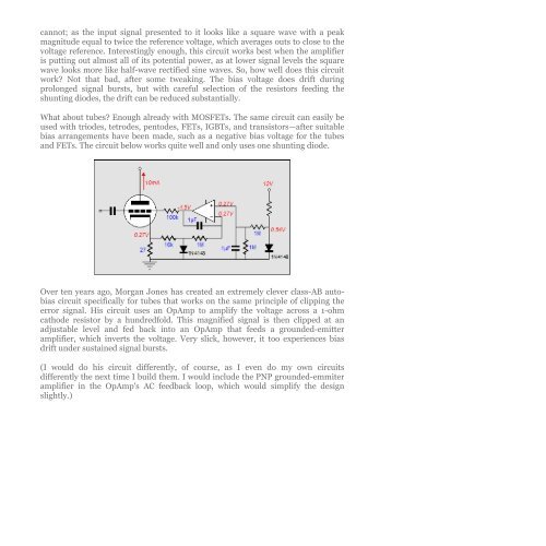
What about tubes Enough already with MOSFETs. The same circuit can easily be<br />
used with triodes, tetrodes, pentodes, FETs, IGBTs, and transistors—after suitable<br />
bias arrangements have been made, such as a negative bias voltage for the tubes<br />
and FETs. The circuit below works quite well and only uses one shunting diode.<br />
Over ten years ago, Morgan Jones has created an extremely clever class-AB autobias<br />
circuit specifically for tubes that works on the same principle of clipping the<br />
error signal. His circuit uses an OpAmp to amplify the voltage across a 1-ohm<br />
cathode resistor by a hundredfold. This magnified signal is then clipped at an<br />
adjustable level and fed back into an OpAmp that feeds a grounded-emitter<br />
amplifier, which inverts the voltage. Very slick, however, it too experiences bias<br />
drift under sustained signal bursts.<br />
(I would do his circuit differently, of course, as I even do my own circuits<br />
differently the next time I build them. I would include the PNP grounded-emmiter<br />
amplifier in the OpAmp's AC feedback loop, which would simplify the design<br />
slightly.)


