19050 Series Hipot Tester AC/DC/IR/SCAN - Chroma Systems ...
19050 Series Hipot Tester AC/DC/IR/SCAN - Chroma Systems ...
19050 Series Hipot Tester AC/DC/IR/SCAN - Chroma Systems ...

You also want an ePaper? Increase the reach of your titles
YUMPU automatically turns print PDFs into web optimized ePapers that Google loves.
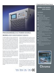
<strong>AC</strong>/<strong>DC</strong>/<strong>IR</strong> <strong>Hipot</strong> <strong>Tester</strong><br />
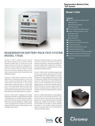
MODEL 19070 SERIES<br />
<strong>19050</strong> SERIES<br />
Basic Specifications:<br />
<strong>AC</strong>/<strong>DC</strong>/<strong>IR</strong> 3 in 1 hipot tester<br />
<strong>AC</strong> 5kV and <strong>DC</strong> 6kV output<br />
1kV insulation resistance test<br />
Insulation resistance measurement from<br />
1M to 50G<br />
Ground continuity check<br />
Standard RS-232 interface<br />
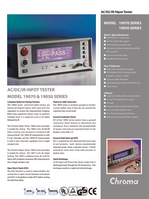
<strong>AC</strong>/<strong>DC</strong>/<strong>IR</strong> HIPOT TESTER<br />
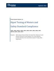
MODEL 19070 & <strong>19050</strong> SERIES<br />
Complete Dielectric Testing Solution<br />
Flashover (ARC) Detection<br />
The <strong>19050</strong> series electrical safety testers are The 19070 series is sensitive enough to monitor<br />
advanced digital hipots with load and line current spikes even if they do not exceed the<br />
regulation to ensure the measurement integrity. maximum trip current level.<br />
Multi-step capability allows users to perform<br />
multiple tests in a sequence such as <strong>AC</strong> hipot Ground Continuity Check<br />
followed by <strong>IR</strong>.<br />
All of the <strong>19050</strong> series testers have a ground<br />
continuity check feature to determine the<br />
The <strong>Chroma</strong> <strong>Hipot</strong> <strong>Tester</strong> <strong>19050</strong> series provides resistance, that is between the ground blade<br />
3 models for choice. The 19052 is for <strong>AC</strong>/<strong>DC</strong>/<strong>IR</strong> of power cord and any exposed metal on the<br />
<strong>Hipot</strong> testing and insulation resistance (<strong>IR</strong>) product, is less than 1.<br />
measurements. The 19053 <strong>IR</strong> measurement is with<br />
8 scan channels, and the 19054 <strong>IR</strong> measurement Ground Fault Interrupt (GFI)<br />
is with 4 scan channels capability into a single GFI is required by the National Electrical Code<br />
compact unit.<br />
in wet locations. Such devices automatically<br />
interrupt power when a ground current > 0.5mA<br />
The <strong>Chroma</strong> <strong>Hipot</strong> <strong>Tester</strong> 19070 series provides existed for more than a few milli-seconds to<br />
2 models for choice. The 19071 is for <strong>AC</strong> <strong>Hipot</strong> protect users.<br />
testing. The 19073 combines both <strong>AC</strong> and <strong>DC</strong><br />
<strong>Hipot</strong> with insulation resistance (<strong>IR</strong>) measurements Quick Discharge<br />
into a single compact unit.<br />
In <strong>DC</strong> hipot and <strong>IR</strong> test the device under test is<br />
discharged back through the HV transformer. This<br />
Open Short Check (OSC)<br />
technique results in a rapid and safe discharge.<br />
The OSC function is used to check whether the<br />
connection is open circuit between instrument<br />
and DUT or breakdown inside DUT before testing<br />
the electrical safety.<br />
Key Features:<br />
Open short check(OSC) function<br />
GFI shutdown the instrument when<br />
imbalance current > 0.5mA<br />
Flashover (ARC) detection<br />
Quick discharge of DUT in <strong>IR</strong> and <strong>DC</strong> test<br />
Pause mode<br />
Others:<br />
Large LCD display (240 x 64 dots matrix)<br />
UL and TUV approved (*see spec)<br />
CE mark<br />
Programmable ramp/fall and test time<br />
Programmable high/low limit<br />
Save/Recall program test function<br />
Remote control and interface support<br />
GPIB RS-232 PRINTER
TECHNICAL NOTE<br />
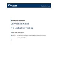
FLASHOVER DETECTION<br />
Fast transient in Voltage or Current occured while Hi-Pot testing is called Electrical Flashover. Normally, in <strong>AC</strong> line frequency (50Hz/60Hz) or <strong>DC</strong> Hi-Pot<br />
testing, the leakage current is the same as 50Hz/60Hz or <strong>DC</strong> (charge current is excepted). As shown in Figure leakage current varies smoothly.<br />
On the other hand, electrical discharge occurred because of poor insulation in material, electrode gap or surface clearance etc., fast transient in leakage<br />
current apparent as shown in figure. This is phenomenon of poor withstanding. Most of Electrical Safety regulations mention the necessity in Withstand<br />
Strength Test. Nevertheless, general Hi-Pot tester detects the RMS value of leakage current only without capability to detect Flashover. Therefore,<br />
FLASHOVER detection function equipped with Hi-Pot tester is necessary.<br />
10<br />
Test Voltage Waveform<br />
Gap Discharge Voltage<br />
10<br />
Test Voltage Waveform<br />
Gap Discharge Voltage<br />
0<br />
0<br />
180 360<br />
180 360<br />
Leakage Current (normal capacitive)<br />
Leakage Current (abnornmal with flashover)<br />
-10<br />
-10<br />
Figure 1 : Normal Leakage Current Waveform<br />
Figure 2 : Leakage Current Waveform when flahover occurred<br />
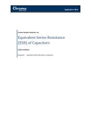
OPEN/SHORT CHECK (OSC)<br />
O.S.C function is used to check the connection is open or short circuit between instrument and DUT(equipment under test) before the Electrical Safety Test.<br />
If the connection is bad between the instrument and DUT, sometimes like leads or relay oxidation, the judgment is also PASS. In some cases, the DUT is<br />
short before testing. Testing continually leads to our instrument broken because suffered the high load current. Therefore, we have to check the open and<br />
short circuit to ensure the test effectively and protect instruments.<br />
Generally, the DUT have capacitive load (Cx) from tens to thousands of pF. If the connection opening, a capacitance will appear and then total capacitive<br />
load is lower than that in normal condition. If the DUT shorting, total capacitive load is higher than that in normal condition. Therefore, we can measure the<br />
value of capactive load to check the contact is good or not.<br />
Hi<br />
Hi<br />
C c<br />
Hi<br />
V s<br />
V<br />
C x<br />
V s V C x<br />
V s<br />
V<br />
µA<br />
Lo<br />
µA<br />
Lo<br />
µA<br />
Lo<br />
Normal Condition<br />
If Circuit Opened :<br />
C = C c *C x /(C c +C x ) > C x<br />
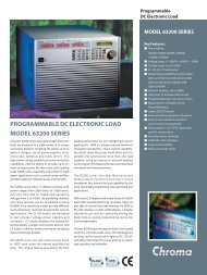
Ground Fault Interrupt (GFI)<br />
The requirement of test environment indicates that test equipment<br />
is equipped with auto interrupt device so that <strong>Chroma</strong> develops into<br />
<strong>Hipot</strong> <strong>Tester</strong><br />
HV<br />
Ground Fault Interrupt (GFI) function. When the current meter A 1<br />
and A 2 detect the difference (i 2 -i 1 =i H ) between the value i 1 and actual<br />
i 2 test current over high, this device can cut the power transiently for<br />
protecting human body safety. It is not only compliance with the safety<br />
standard but also more safeguards for test personnel.<br />
i 2 i 1<br />
A2 A1<br />
Return<br />
DUT<br />
Operator<br />
i H
PANEL DESCRIPTION<br />
19073<br />
2 5<br />
20<br />
3<br />
4<br />
1<br />
6 23 7 8 9 11 10<br />
10 14 11 22 15 19<br />
19053<br />
2 5 6 7 8<br />
19 14 13 22 20 17 18<br />
3<br />
9<br />
4<br />
1<br />
10<br />
11<br />
12 23<br />
16 15 21<br />
1. LINE Switch<br />
2. Window Display<br />
3. Stop Button<br />
4. Start Button<br />
5. Function Keys (F1~F4)<br />
6. Calibration Switch<br />
7. Pass Indicator<br />
8. Fail Indicator<br />
9. Test Indicator<br />
10. HV Output<br />
11. RTN/LOW<br />
12. 8 channels HV Output<br />
(19053 only)<br />
13. Remote I/O<br />
14. LINE Voltage Selector<br />
15. Power Cord Receptacle<br />
16. RTN/LOW<br />
17. GPIB/Printer Interface (Option)<br />
18. Scan Interface (Option)<br />
19. Fan<br />
20. Remote Interface<br />
21. RS-232 Interface<br />
22. Continuity Test O/P<br />
23. Update Switch<br />
APPLICATION<br />
Production test of appliances, instruments and information technology equipment in accordance with UL, IEC, TUV and other standards such<br />
as EN 60335, EN 60950, EN 61010, CSA C22.2 No.1010.1, UL 3111 and UL 1950<br />
Transformer electrical safety test<br />
Electric motor safety test<br />
Various electronic components tests<br />
ORDERING INFORMATION<br />
19071 : <strong>AC</strong> <strong>Hipot</strong> <strong>Tester</strong><br />
19073 : <strong>AC</strong>/<strong>DC</strong>/<strong>IR</strong> <strong>Hipot</strong> <strong>Tester</strong><br />
19073 : <strong>AC</strong>/<strong>DC</strong>/<strong>IR</strong> <strong>Hipot</strong> <strong>Tester</strong> with RS485<br />
A190701 : Remote Control Box<br />
A190702 : 40kV Test Probe<br />
A190344 : HV Gun (SP02)<br />
A190706 : 19" Rack Mount Kit<br />
19052 : <strong>Hipot</strong> <strong>Tester</strong> (<strong>AC</strong>/<strong>DC</strong>/<strong>IR</strong>)<br />
19053 : <strong>Hipot</strong> <strong>Tester</strong> (<strong>AC</strong>/<strong>DC</strong>/<strong>IR</strong>/ 8CH <strong>SCAN</strong>)<br />
19054 : <strong>Hipot</strong> <strong>Tester</strong> (<strong>AC</strong>/<strong>DC</strong>/<strong>IR</strong>/ 4CH <strong>SCAN</strong>)<br />
A190512 : Auto Control TR. Scan Box<br />
A<strong>19050</strong>8 : GPIB Interface<br />
A190344 : HV Gun (SP02)<br />
A150517 : 19" Rack Mount Kit
SPECIFICATIONS<br />
Model 19071 19073 19052 19053 19054<br />
Mode <strong>AC</strong> <strong>AC</strong>/<strong>DC</strong>/<strong>IR</strong> <strong>AC</strong>/<strong>DC</strong>/<strong>IR</strong> <strong>AC</strong>/<strong>DC</strong>V/<strong>IR</strong>/<strong>SCAN</strong> <strong>AC</strong>V/<strong>DC</strong>V/<strong>IR</strong>/<strong>SCAN</strong><br />
Scanner Unit - - - 8 ports,±phase 4 ports,±phase<br />
Withstanding Voltage Test<br />
Output Voltage<br />
<strong>AC</strong> : 0.05 ~ 5kV, <strong>DC</strong> : 0.05 ~ 6kV<br />
Load Regulation<br />
1% of setting + 5V<br />
Voltage Resolotion<br />
2V<br />
Voltage Accuracy<br />
1% of setting + 5 count<br />
Cutoff Current <strong>AC</strong> : 0.1~20mA,<strong>DC</strong> : 0.01 ~ 5mA <strong>AC</strong> : 0.1 ~ 30mA, <strong>DC</strong> : 0.01 ~ 10mA<br />
Current Resolution<br />
<strong>AC</strong> : 1µA, <strong>DC</strong> : 0.1µA<br />
Current Accuracy<br />
1% of setting + 5 count<br />
Output Frequency<br />
50Hz / 60Hz<br />
Test Time<br />
0.3 ~ 999 sec., continue<br />
Ramp Time<br />
0.1 ~ 999 sec., off<br />
Fall Time<br />
0.1 ~ 999 sec., off<br />
Dwell Time<br />
0.1 ~ 999 sec., off<br />
Waveform<br />
Sine wave<br />
Insulation Resistance<br />
Output Voltage - <strong>DC</strong> : 0.05 ~ 1kV<br />
Voltage Resolution - 2V<br />
Voltage Accuracy - 1% Reading + 1% Full Scale<br />
<strong>IR</strong> Range - 1M~50G 1M~10G<br />
1.00M~ 25.00M -<br />
Resistance<br />
Accuracy<br />
≥ 500V<br />
*All specifications are subject to change without notice.<br />
22.0 M~250.0M -<br />
± (5% of reading + 2% of full scale)<br />
0.220G~1.000G - ± (5% of reading + 5% of full scale)<br />
1.000G~2.500 G - ± (10% of reading + 2% of full scale)<br />
2.20G~10.00G - ± (15% of reading + 5% of full scale)<br />
10.00G~50.00G - ± (15% of reading + 1% of scale) -<br />
0.10 M~25.00M -<br />
≤ 500V 22.0M~250.0M -<br />
± (10% of reading + 2% of full scale)<br />
0.220 G~1.000G - ± (10% of reading + 5% of full scale)<br />
Flashover (ARC) Detection<br />
Setting Mode<br />
Programmable setting<br />
Detection Current <strong>AC</strong> : 1mA ~ 15mA, <strong>DC</strong> : 1mA ~ 5mA <strong>AC</strong> : 1mA ~ 15mA, <strong>DC</strong> : 1mA ~ 10mA<br />
Secure Protection Function<br />
Fast Output Cut-off<br />
0.4ms after NG happen<br />
Ground Fault Interrupt<br />
0.5mA ±0.25mA <strong>AC</strong>, ON/OFF<br />
Panel Operation Lock<br />
Present password<br />
Continuity Check<br />
1 ± 0.2, ON/OFF<br />
GO/NG Judgment Window<br />
Indication, Alarm<br />
GO : Short sound, Green LED ; NG : Long sound, Red LED<br />
Data Hold<br />
Least tests data memories<br />
Memory Storage 60 steps in 60 groups 500 steps in 99 groups<br />
Remote & Interface<br />
Remote control<br />
Input : Start, Stop, Interlock (at 11 pin terminal block only) ; Output : Under test, Pass, Fail<br />
Communication Interface RS485 (Option) RS232 (Standard), GPIB (Option).<br />
General<br />
Operation Environment<br />
Temperature : 0°C~40°C, Humidity : 15% to 95% R.H@≤40°C<br />
Power Requirements<br />
100V/120V/220V/240V (<strong>AC</strong> ±10%), 50/60Hz<br />
Power Consumption 300W 500W<br />
Dimension (W x H x D) 270 x 105 x 350 mm 320 x 105 x 400 mm<br />
Weight Approx.12 KG Approx.15 kg<br />
Certification UL,TUV,CE UL,TUV,CE CE UL,TUV,CE<br />
Developed and Manufactured by :<br />
CHROMA ATE INC.<br />
致 茂 電 子 股 份 有 限 公 司 CHINA<br />
HEADQUARTERS<br />
CHROMA ELECTRONICS<br />
No. 66, Hwa-Ya 1st Rd., (SHENZHEN) CO., LTD.<br />
Hwa-Ya Technology Park, 8F, No.4, Nanyou Tian An<br />
Kuei-Shan Hsiang,33383 Industrial Estate, Shenzhen,<br />
Taoyuan County, Taiwan China PC: 518052<br />
Tel: +886-3-327-9999 Tel: +86-755-2664-4598<br />
Fax: +886-3-327-8898 Fax: +86-755-2641-9620<br />
http://www.chromaate.com<br />
E-mail: info@chromaate.com<br />
JAPAN<br />
CHROMA JAPAN CORP.<br />
472 Nippa-cho, Kouhoku-ku,<br />
Yokohama-shi, Kanagawa,<br />
223-0057 Japan<br />
http://www.chroma.co.jp<br />
E-mail: info@chromaate.com<br />
U.S.A.<br />
CHROMA SYSTEMS<br />
SOLUTIONS, INC.<br />
25612 Commercentre Drive,<br />
Lake Forest, CA 92630-8830<br />
Tel: +1-949-600-6400<br />
Fax: +1-949-600-6401<br />
Toll Free: +1-866-600-6050<br />
http://www.chromausa.com<br />
E-mail: sales@chromausa.com<br />
EUROPE<br />
CHROMA ATE EUROPE B.V.<br />
Morsestraat 32, 6716 AH Ede,<br />
The Netherlands<br />
Tel: +31-318-648282<br />
Fax: +31-318-648288<br />
http://www.chromaeu.com<br />
E-mail: sales@chromaeu.com<br />
Distributed by:<br />
Worldwide Distribution and Service Network<br />
19070+<strong>19050</strong>-E-201108-1000