Laser Speckle Extensometer ME53 - Messphysik
Laser Speckle Extensometer ME53 - Messphysik
Laser Speckle Extensometer ME53 - Messphysik

You also want an ePaper? Increase the reach of your titles
YUMPU automatically turns print PDFs into web optimized ePapers that Google loves.
PDS 161 J en<br />
ALTENMARKT 180, 8280 FÜRSTENFELD<br />
TEL.: +43 3382-54060-0 FAX: -27<br />
AUSTRIA, EUROPE<br />
WWW.MESSPHYSIK.COM<br />
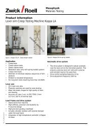
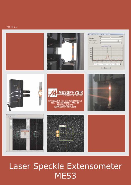
<strong>Laser</strong> <strong>Speckle</strong> <strong>Extensometer</strong><br />
<strong>ME53</strong>
INTRODUCTION<br />
When establishing the mechanical properties of today’s diverse range of materials and components it is<br />
necessary to use accurate testing machines and instrumentation that do not influence the results.<br />
Stress and strain are the two main parameters from which most mechanical properties are calculated<br />
during uniaxial testing. Stress is normally obtained by fixing a test specimen in grips or adapters and<br />
loading via a calibrated load cell. Care must be taken to ensure that neither the fixation method, nor<br />
alignment, nor specimen shape influence the results obtained.<br />
For rigid materials, strain can be measured using conventional ‘clip-on’ mechanical extensometers or by<br />
bonding foil gauges to the specimen. These devices however are not usually suitable when testing delicate<br />
specimens such as fibres, films, foils, foams or soft plastics as their weight and method of attachment can<br />
influence both the results obtained and the point of rupture.<br />
In many instances it is necessary to establish the material properties over large strain ranges up to the<br />
point of rupture and most mechanical devices have a limited travel and require removal from the specimen<br />
prior to fracture. If a specimen is to be tested at elevated temperature within a confined chamber, then this<br />
can restrict the use of many mechanical units.<br />
Various non-contacting extension measuring systems e.g. mechanically driven followers and laser<br />
extensometers have been available over latter years, but these systems do not have the necessary<br />
resolution to accurately determine the material properties at low strain levels. Also as the devices operate<br />
on a single measuring line between targets a second unit would be required if the transverse strain had to<br />
be simultaneously measured.<br />
In order to overcome these limitations, the ME-53 <strong>Laser</strong> <strong>Speckle</strong> <strong>Extensometer</strong> was developed by the<br />
Austrian company <strong>Messphysik</strong> GmbH, on the basis that “If it can be seen, then it can be measured”. It's an<br />
easy to use class 1 measurement system, having the capability to measure very small strains and high<br />
strains, completely contact-free.<br />
This enables the usage in a wide range of applications, including applications using elevated<br />
temperatures.<br />
-2-
MEASUREMENT PRINCIPLE<br />
When an optically rough surface is hit by a coherent laser beam, the light will be dispersed in many different<br />
directions. Where these rays travel through the original beam the light will be spatially 'eliminated’,<br />
resulting in a granular looking, so called <strong>Speckle</strong> Pattern.<br />
Dispersion of a laser beam hitting an<br />
optically rough surface<br />
The surface of the specimen and therefore the <strong>Speckle</strong> Pattern change comparatively slowly during<br />
loading. Due to this fact the Video Processor is able to find an initially stored reference-pattern in<br />
consecutive images and measure the distance this pattern has moved in the meantime.<br />
Applying this procedure iteratively from image to image in real-time, (true) strain within the distance of the<br />
two cameras can be measured. With each cycle a new reference-pattern will be taken from the image, but<br />
always at the same coordinates.<br />
� dSlave ��<br />
dMaster<br />
� �<br />
l<br />
� Master<br />
with d .....Sum of displacements<br />
on Master Camera<br />
� dSlave<br />
.......Sum of displacements<br />
on Slave Camera<br />
l0<br />
.................Distance of initial<br />
reference patterns<br />
0<br />
-3-<br />
Typical speckle pattern
EVALUATION ALGORITHM<br />
The fundamental task of the <strong>Laser</strong> <strong>Speckle</strong> <strong>Extensometer</strong>’s software is to recognize a complex pattern (i.e.<br />
region of the video image) in consecutive images. To accomplish these highly intensive calculations stateof-the-art<br />
computers are used for Video Processors on one hand and carefully programmed algorithms<br />
employed on the other hand. First the analogue video images have to be transformed into digital images by<br />
means of a so called Frame Grabber. Built into the Video Processor this special hardware translates the<br />
video signal into a two-dimensional matrix with 756x576 elements (pixels) with 256 grey shades each at a<br />
rate of 25 frames per second. But it is neither necessary nor possible to analyse the entire video image in<br />
real-time a region of variable position and size is sufficient enough.<br />
These regions also function as virtual markers, between which strain is measured as explained earlier.<br />
This involves the calculation of the displacements of these markers from frame to frame.<br />
The regions of the entire pattern can also be understood as sub-matrices or two-dimensional, discrete<br />
functions f �x, y�<br />
. Let f �x, y�<br />
be the function of a reference pattern and g �x, y��f�x��,<br />
y ���<br />
the<br />
mathematical representation of the shifted pattern, then the so-called Correlation Function<br />
f x,<br />
y � g x,<br />
y yields the distance the pattern has travelled.<br />
� � � �<br />
Solving the necessary equations requires<br />
sophisticated two-dimensional discrete<br />
Fast Fourier Transformations (FFTs) and<br />
interpolation techniques to eventually<br />
obtain highly accurate and reproducible<br />
results.<br />
-4-<br />
Two-dimensional correlation function applied<br />
to sequential speckle patterns
SYSTEM COMPONENTS<br />
The <strong>Laser</strong> <strong>Speckle</strong> <strong>Extensometer</strong> comprises a PC-based Video Processor, which continually measures<br />
the displacement of two speckle patterns, recorded by two video cameras in a master-slaveconfiguration.<br />
These two displacements are converted into a strain signal, which is sent to a control and<br />
evaluation system (not part of the extensometer) for data handling and control of the testing machine.<br />
<strong>Laser</strong><br />
Diodes<br />
Testing Machine<br />
Video Cameras<br />
S<br />
-5-<br />
M<br />
System
PARALLEL SENSOR HEAD<br />
HARDWARE<br />
This sensor head comprises two full image cameras for uni- or bi-axial strain measurement with the <strong>Laser</strong><br />
<strong>Speckle</strong> <strong>Extensometer</strong> <strong>ME53</strong> series (in both tension and compression mode).<br />
The arbitrary adjustment of the cameras along the vertical axis allows a wide range of different initial<br />
gauge lengths. The servo drive is designed to make the system easy to handle by software. It can also be<br />
used to set gauge lengths automatically in a process controlled loop.<br />
TECHNICAL SPECIFICATIONS<br />
- ISO 9513 Class 1 strain measurement system<br />
- Working distance g: 180 - 630 mm<br />
- Optical magnification: 0.5 (g=630 mm)<br />
2.4 (g=180 mm)<br />
- Gauge length range: 1.5 - 230 mm<br />
- Mass of sensor head: 4.6 kg<br />
- <strong>Laser</strong> light source: Class 2, 0.9 mW, 635 nm (red laser light)<br />
- Software remote control of camera settings and gauge length<br />
-6-
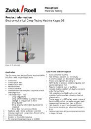
SOFTWARE<br />
Core part of the <strong>Laser</strong> <strong>Speckle</strong> <strong>Extensometer</strong> is its software. This 32-bit programme, requiring Windows<br />
XP/VISTA, has been developed to provide a simple and easy to handle user interface without restricting<br />
functionality. Most frequently used functions can be accessed with “a touch of a button”.<br />
Both the master and the slave cameras’ video images are displayed in separate windows.<br />
A big advantage of utilizing area scan sensors instead of line cameras is, that you can actually see,<br />
where the virtual markers are placed. You can either have their “best” position recognized<br />
automatically or you can move them around yourself.<br />
-7-
SYSTEM INTEGRATION<br />
In many cases the <strong>Laser</strong> <strong>Speckle</strong> <strong>Extensometer</strong> will be integral part of an entirely new <strong>Messphysik</strong><br />
Materials Testing system. But the capability to integrate it into virtually any existing third party system,<br />
enables you to work with this exciting new technology without having to purchase a new loading frame or<br />
controller.<br />
DIGITAL LINK<br />
The Video Processor is linked to the<br />
controlling computer via a digital interface<br />
(RS232, LAN). When not using one of<br />
<strong>Messphysik</strong>’s Application Programmes,<br />
you must have access to your<br />
programme’s source code and the ability<br />
to integrate a so-called Dynamic Link<br />
Library (DLL).<br />
DIGITAL-TO-ANALOGUE CONVERSION<br />
The digital extension or strain signal<br />
obtained by the <strong>Laser</strong> <strong>Speckle</strong><br />
<strong>Extensometer</strong> is converted into an<br />
analogue signal by means of an optional<br />
digital-to-analogue converter. These<br />
voltages can be fed into the controller of<br />
your testing machine and/or sent to a chart<br />
recorder.<br />
-8-
ANALOGUE-TO-DIGITAL CONVERSION<br />
SYSTEM INTEGRATION<br />
Analogue signals for load, stroke or other readings can be fed into an optional analogue-to-digital<br />
converter built into the Video Processor. There these voltages are translated into figures,<br />
which are stored into files in perfect correlation with the strain measured by the <strong>Laser</strong> <strong>Speckle</strong><br />
<strong>Extensometer</strong>.<br />
These ASCII files can be post-processed by either one of <strong>Messphysik</strong>’s Application Programmes or a<br />
multitude of third party programmes (e.g. Microsoft® Excel).<br />
-9-
TRANSVERSE STRAIN<br />
SYSTEM VARIANTS & OPTIONS<br />
One of the biggest advantages of utilizing full image<br />
cameras instead of line cameras is their twodimensionality<br />
and therefore the possibility to<br />
measure strain in two dimensions.<br />
Although it would also be possible for line camera<br />
systems to measure axial and transverse strain<br />
simultaneously, but this would require a total of 4<br />
cameras.<br />
The <strong>Laser</strong> <strong>Speckle</strong> <strong>Extensometer</strong> on the other hand<br />
can achieve the same with two or even one camera<br />
only.<br />
Two additional patterns are introduced into the<br />
system to measure transverse strain.<br />
SINGLE CAMERA CONFIGURATION<br />
Most applications will require a two camera setup:<br />
In order to achieve initial gauge lengths of more<br />
than 25mm it is necessary to use two cameras<br />
either mounted in a fixed distance equalling the<br />
initial gauge length or on a Parallel Sensor Head<br />
enabling variable gauge lengths. Each camera<br />
provides its own single speckle pattern based on<br />
whose displacement strain is calculated during<br />
testing.<br />
However, where initial gauge lengths smaller than<br />
25mm are required a single camera solution can<br />
also be employed: The two necessary speckle<br />
patterns are recorded by only one camera with a<br />
suitable field of view. This does not only provide<br />
cost savings but also facilitates the handling of the<br />
<strong>Laser</strong> <strong>Speckle</strong> <strong>Extensometer</strong> in cases of small to<br />
very small gauge lengths: It is not longer necessary<br />
to adjust the distance or the angle between the two<br />
cameras, only one camera has to be calibrated etc.<br />
-10-<br />
Transversal strain measurement configuration<br />
Testing at small to very<br />
small gauge lengths can<br />
be carried out by means<br />
of a single camera<br />
configuration.<br />
In the application shown<br />
alogside , the initial gauge<br />
length was 1mm only.<br />
Single Camera Configuration
SYSTEM VARIANTS & OPTIONS<br />
DIAMETRIC STRAIN MEASUREMENT<br />
A versatile optional feature of the <strong>Laser</strong> <strong>Speckle</strong> <strong>Extensometer</strong> is the ability to simultaneously process<br />
signals from two sensor heads.<br />
The second sensor head can be mounted opposite the first one to<br />
eliminate any effects caused by bending stresses e.g. When<br />
testing bent specimens. It is possible to measure with two different<br />
or offset gauge lenghts.<br />
BIAXIAL MEASUREMENT<br />
SPECIFICATIONS<br />
Axial strain measurement under coherent light by means of <strong>Laser</strong> <strong>Speckle</strong> <strong>Extensometer</strong><br />
Simultaneous transverse strain measurement under incoherent light with Videoextensometer<br />
Videoextensometer scans profile of specimen to determine R-Value and/or necking and reduction of<br />
area before break<br />
SYSTEM REQUIREMENTS<br />
<strong>Laser</strong> <strong>Speckle</strong> <strong>Extensometer</strong> D/DT<br />
Multiple Video Sensor Option<br />
Second Dimension including light screen<br />
2x Dielectric Filters<br />
(for <strong>Laser</strong> <strong>Speckle</strong> <strong>Extensometer</strong> Cameras)<br />
1x <strong>Laser</strong> Cut Out Filter<br />
(for Videoextensometer Camera)<br />
-11-
APPLICATIONS<br />
Because of the non-contacting nature of the <strong>Laser</strong> <strong>Speckle</strong> <strong>Extensometer</strong> and due to the fact that it makes<br />
markings unnecessary, this new type of extensometer allows direct strain measurement on materials or in<br />
environments never possible before.<br />
Measuring E-Moduli of delicate materials such as thin films or metal foils do no longer pose problems nor<br />
will elevated or high temperatures - the <strong>Laser</strong> <strong>Speckle</strong> <strong>Extensometer</strong> is the ultimate solution.<br />
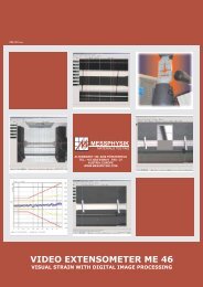
HF-GENERATOR INDUCED HIGH<br />
TEMPERATURE<br />
Measuring strain of metals at high temperatures is one of the<br />
most demanding tasks in materials testing. Contacting<br />
extensometers can notch the softened specimen. The actual<br />
gauge has to be placed outside the furnace with silica rods<br />
reaching through port holes levers that can bias the results<br />
dramatically. Markers for non-contacting devices can not be<br />
attached because they would burn off.<br />
Another problem can be the long preparation times for each<br />
test with heating as the most time consuming part.<br />
As successful solution for both problems <strong>Messphysik</strong><br />
developed a system incorporating a High Frequency<br />
Generator instead of a standard furnace and the <strong>Laser</strong><br />
<strong>Speckle</strong> <strong>Extensometer</strong> to measure strain within the heated<br />
zone.<br />
Due to its unique design of arbitrary but fixed gauge lengths<br />
(i.e. the distance between the virtual markers does not<br />
change), the <strong>Laser</strong> <strong>Speckle</strong> <strong>Extensometer</strong> can “look”<br />
through the helices of the induction coil.<br />
-12-
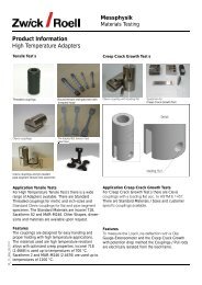
FULLY AUTOMATED TESTING SYSTEMS<br />
APPLICATIONS<br />
Due to its simple design with the lack of any moving parts \and its high degree of system<br />
integration the <strong>Laser</strong> <strong>Speckle</strong> <strong>Extensometer</strong> is predestined for fully automated, high throughput<br />
testing systems.<br />
-13-
Vertical Positioning Unit<br />
ACCESSORIES<br />
The Vertical Positioning Unit was designed to set up the height of the<br />
Sensor Head easily, but also to prevent from having breaks outside the<br />
measuring length of the extensometer.<br />
Duo to most machines do not tear the specimen in two directions but only in<br />
one, the vertical positioning unit ensures that the extensometer is always<br />
located in the middle of the specimen.<br />
The vertical positioning unit comprises:<br />
A precision slide to carry the Sensor Head, allowing vertical movement<br />
but no radial freedom.<br />
The slide is linked via a drive pulley to the moving and to the fixed<br />
crosshead. This ensures that the sensor head travels exactly half of the<br />
stroke of the moving cross head.<br />
Consequently the sensor head will measure strain symmetrically within<br />
the parallel length of the specimen throughout the entire test.<br />
Recommendations:<br />
This optional unit is recommended for<br />
testing of mild steel and ther ductile<br />
metals with a tendency to necking.<br />
It is absolute necessary for testing of<br />
polymers with a breaking extension<br />
>50 % (e. g. Rubber).<br />
This unit is also applicable to the<br />
Videoextensometer ME 46 and ME46-<br />
NG.<br />
-14-
Class1 measurement device (ISO 9513)<br />
Initial Gauge Length: 0mm ��<br />
Measuring Range: �<br />
SPECIFICATIONS<br />
Temperature Range of Test Specimen: up to 1600°C<br />
(requires observation ports in furnace and optional band<br />
width filter)<br />
<strong>Laser</strong> Diodes: 635nm / 0.9 mW, Class 2<br />
-15-
Contact free<br />
ADVANTAGES<br />
No specimen preparation or markers needed<br />
No moving parts, maintenance free<br />
Two-dimensionality<br />
Arbitrary initial gauge lengths, indefinite measuring range<br />
Testing temperatures up to 1500°C<br />
High degree of automation and system integration<br />
Measuring E-Moduli and breaking strains with a single system<br />
User friendly software