Variable speed drives Altivar 31 - Telmak
Variable speed drives Altivar 31 - Telmak
Variable speed drives Altivar 31 - Telmak

You also want an ePaper? Increase the reach of your titles
YUMPU automatically turns print PDFs into web optimized ePapers that Google loves.
Functions (continued) 1<br />
<strong>Variable</strong><br />
<strong>speed</strong> <strong>drives</strong><br />
for asynchronous motors 1<br />
<strong>Altivar</strong> <strong>31</strong><br />
Drive factory setting<br />
The drive is supplied ready for use in most applications, with the following functions<br />
and settings:<br />
b Nominal motor frequency: 50 Hz<br />
b Motor voltage: 230 V (ATV <strong>31</strong>HpppM2 and M3X), 400 V (ATV <strong>31</strong>HpppN4) or<br />
600 V (ATV <strong>31</strong>HpppS6X)<br />
b Linear ramp times: 3 seconds<br />
b Low <strong>speed</strong> (LSP): 0 Hz, high <strong>speed</strong> (HSP): 50 Hz<br />
b Normal stop mode on deceleration ramp<br />
b Stop mode in the event of a fault: Freewheel<br />
b Motor thermal current = nominal drive current<br />
b Standstill injection braking current = 0.7 x nominal drive current, for 0.5 seconds<br />
b Constant torque operation, with sensorless flux vector control<br />
b Logic inputs:<br />
v 2 directions of operation (LI1, LI2), 2-wire control<br />
v 4 preset <strong>speed</strong>s (LI3, LI4): LSP (low <strong>speed</strong>), 10 Hz, 15 Hz, 20 Hz<br />
b Analog inputs:<br />
v AI1 <strong>speed</strong> reference (0 +10 V)<br />
v AI2 (0 ± 10 V) summing of AI1<br />
v AI3 (4-20 mA) not configured<br />
b Relay R1: fault relay<br />
b Relay R2: not assigned<br />
b Analog output AOC: 0-20 mA, image of the motor frequency<br />
b Automatic adaptation of the deceleration ramp in the event of excessive braking<br />
b Switching frequency 4 kHz, random frequency<br />
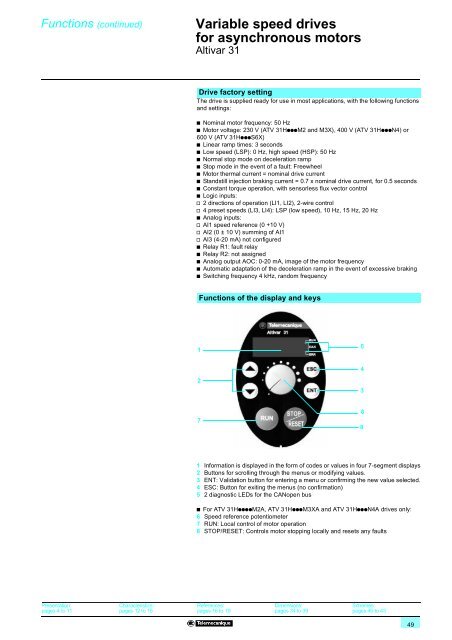
Functions of the display and keys<br />
1<br />
5<br />
4<br />
2<br />
3<br />
7<br />
6<br />
8<br />
1 Information is displayed in the form of codes or values in four 7-segment displays<br />
2 Buttons for scrolling through the menus or modifying values.<br />
3 ENT: Validation button for entering a menu or confirming the new value selected.<br />
4 ESC: Button for exiting the menus (no confirmation)<br />
5 2 diagnostic LEDs for the CANopen bus<br />
b For ATV <strong>31</strong>HppppM2A, ATV <strong>31</strong>HpppM3XA and ATV <strong>31</strong>HpppN4A <strong>drives</strong> only:<br />
6 Speed reference potentiometer<br />
7 RUN: Local control of motor operation<br />
8 STOP/RESET: Controls motor stopping locally and resets any faults<br />
Presentation:<br />
pages 4 to 11<br />
Characteristics:<br />
pages 12 to 15<br />
References:<br />
pages 16 to 19<br />
Dimensions:<br />
pages 34 to 39<br />
Schemes:<br />
pages 40 to 43<br />
49