Custom Tank Design - Moeller Marine Online
Custom Tank Design - Moeller Marine Online
Custom Tank Design - Moeller Marine Online

Create successful ePaper yourself
Turn your PDF publications into a flip-book with our unique Google optimized e-Paper software.
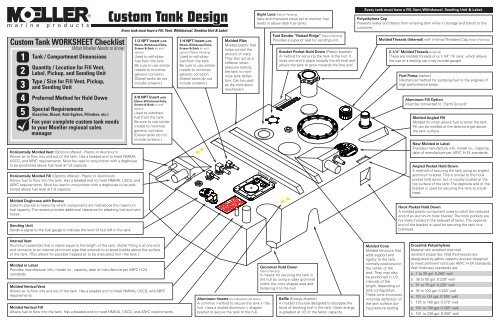
Horizontally Molded Vent (Options offered - Plastic or Aluminum)<br />
Allows air to flow into and out of the tank. Has a beaded end to meet NMMA,<br />
USCG, and ABYC requirements. Must be used in conjunction with a doghouse<br />
to be positioned above fuel level at full capacity.<br />
Horizontally Molded Fill (Options offered - Plastic or Aluminum)<br />
Allows fuel to flow into the tank. Has a beaded end to meet NMMA, USCG, and<br />
ABYC requirements. Must be used in conjunction with a doghouse to be positioned<br />
above fuel level at full capacity.<br />
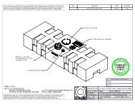
Molded Doghouse with Recess<br />
Used to provide a means by which components are held above the maximum<br />
fuel capacity. The recess provides additional clearance for attaching fuel and vent<br />
hoses.<br />
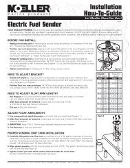
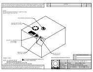
Sending Unit<br />
Sends a signal to the fuel gauge to indicate the level of fuel left in the tank.<br />
Molded in Label<br />
Provides manufacturer info, model no., capacity, date of manufacture per ABYC H-24<br />
standards.<br />
1/2 NPT Insert with<br />
Elbow, Withdrawal Tube,<br />
Screen & Barb (or antisiphon)<br />
Used to withdraw<br />
fuel from the tank.<br />
Be sure to use similar<br />
metals to minimize<br />
galvanic corrosion.<br />
(Diesel tanks do not<br />
include screens.)<br />
3/8 NPT Insert with<br />
Elbow, Withdrawal Tube,<br />
Screen & Barb (or antisiphon)<br />
Used to withdraw<br />
fuel from the tank.<br />
Be sure to use similar<br />
metals to minimize<br />
galvanic corrosion.<br />
(Diesel tanks do not<br />
include screens.)<br />
Internal Vent<br />
Aluminum assembly that is nearly equal to the length of the tank. Outlet fitting is at one end<br />
and connects to an internal aluminum pipe that extends to a raised bubble above the surface<br />
of the tank. (This allows for possible trapped air to be evacuated from the tank.)<br />
Molded Vertical Vent<br />
Allows air to flow into and out of the tank. Has a beaded end to meet NMMA, USCG, and ABYC<br />
requirements.<br />
Molded Vertical Fill<br />
Allows fuel to flow into the tank. Has a beaded end to meet NMMA, USCG, and ABYC requirements.<br />
1/4 NPT Insert with<br />
Elbow, Withdrawal Tube,<br />
Screen & Barb (or antisiphon)<br />
(Patent Pending)<br />
Used to withdraw<br />
fuel from the tank.<br />
Be sure to use similar<br />
metals to minimize<br />
galvanic corrosion.<br />
(Diesel tanks do not<br />
include screens.)<br />
Molded Ribs<br />
Molded plastic that<br />
helps control the<br />
amount of warp.<br />
They also act as a<br />
stiffener when<br />
pressure testing<br />
the tank to minimize<br />
tank deflection.<br />
Can be used<br />
as the hold down<br />
mechanism.<br />
FULL<br />
EMPTY<br />
Aluminum Inserts (for L-Bracket hold down)<br />
A common method to secure the tank in the<br />
hull. Uses a slotted aluminum L shaped<br />
bracket to secure the tank to the hull.<br />
Sight Lens (Patent Pending)<br />
New and improved visual aid to monitor fuel<br />
levels in above deck fuel tanks.<br />
Cluster Plate<br />
Fuel Sender “Raised Ridge” (Patent Pending)<br />
Provides a superior seal for sending unit.<br />
Bracket Pocket Hold Down (Plastic bracket)<br />
A method for securing the tank in the hull. It<br />
locks one end in place (usually the aft end) and<br />
allows the tank to grow towards the fore end.<br />
Grommet Hold Down<br />
Patent Pending<br />
A means for securing the tank in<br />
the hull by using a ruber grommet<br />
within the cone shaped area and<br />
fastening it to the hull.<br />
Baffle (Energy diverter)<br />
A molded structure designed to dissipate the<br />
force of sloshing fuel in the tank. Slosh energy<br />
is greatest at 1/2 of the tanks’ capacity.<br />
Every tank must have a Fill, Vent, Withdrawal, Sending Unit & Label.<br />
Polyethylene Cap<br />
Prevents water and debris from entering tank while in storage and transit to the<br />
customer.<br />
Molded Threads (Internal) with Internal Threaded Cap (Patent Pending)<br />
Molded Cone<br />
Molded structure that<br />
adds support and<br />
rigidity to the tank,<br />
normally positioned in<br />
the center of the<br />
tank. They may also<br />
be positioned in 1/3<br />
intervals of the<br />
length, depending on<br />
tank configuration.<br />
These cone structures<br />
minimize deflection of<br />
the tank surface during<br />
pressure testing.<br />
2-1/4” Molded Threads (external)<br />
These are molded threads on a 1-1/4” fill neck, which allows<br />
the use of a sealing cap (may include gauge).<br />
Fuel Pump (option)<br />
Mechanical method for pumping fuel to the engines of<br />
high performance boats.<br />
Aluminum Fill Option<br />
Must be connected to “Earth Ground”.<br />
Molded Angled Fill<br />
Molded fill which allows fuel to enter the tank.<br />
Fill can be molded at the desired angle above<br />
the tank surface.<br />
New Molded in Label<br />
Provides manufacture info, model no., capacity,<br />
date of manufacture per ABYC H-24 standards.<br />
Angled Pocket Hold Down<br />
A method of securing the tank using an angled<br />
aluminum bracket. This is similar to the hook<br />
pocket hold down, but is usually located at the<br />
top surface of the tank. The opposite end of the<br />
bracket is used for securing the tank to a bulkhead.<br />
Hook Pocket Hold Down<br />
A molded plastic component used to catch the radiused<br />
end of an aluminum hook bracket. The hook pockets are<br />
normally molded in the sidewall of tanks. The opposite<br />
end of the bracket is used for securing the tank to a<br />
bulkhead.<br />
Crosslink Polyethylene<br />
Material with excellent chemical<br />
resistant properties. Wall thicknesses are<br />
designated by gallon capacity and are designed<br />
to meet pertinent tests per ABYC H-24 standards.<br />
Wall thickness standards are:<br />
a. 1 to 35 gal: 0.200" wall<br />
b. 36 to 50 gal: 0.220" wall<br />
c. 51 to 75 gal: 0.235" wall<br />
d. 76 to 100 gal: 0.250" wall<br />
e. 101 to 124 gal: 0.265" wall<br />
f. 125 to 160 gal: 0.275" wall<br />
g. 161 to 190 gal: 0.285" wall<br />
h. 191 to 230 gal: 0.300" wall