Rebuilding a Scott Allwave 23 - Antique Radio Classified
Rebuilding a Scott Allwave 23 - Antique Radio Classified
Rebuilding a Scott Allwave 23 - Antique Radio Classified

Create successful ePaper yourself
Turn your PDF publications into a flip-book with our unique Google optimized e-Paper software.
RESTORATION TOPICS<br />
<strong>Rebuilding</strong> A <strong>Scott</strong> <strong>Allwave</strong> <strong>23</strong><br />
When a collector rises to the challenge of a<br />
difficult restoration, the rest of us like to hear about it<br />
and have an opportunity to admire, maybe even<br />
emulate, the work. Frank Drost gives us that opportunity<br />
in the following article. (Editor)<br />
Several years ago, as a new collector, I passed<br />
on buying a <strong>Scott</strong> <strong>Allwave</strong> <strong>23</strong> in a nice Tasman<br />
cabinet just because I thought that a <strong>Scott</strong> would be<br />
too much of a challenge for me to rebuild. I went on<br />
to buy and restore many complicated radios, such<br />
as my Philco 680 and 690 sets, and had no apprehension<br />
about rebuilding them.<br />
Then one Saturday morning, I stopped into Great<br />
Northern <strong>Antique</strong> <strong>Radio</strong>s in Minneapolis, and found<br />
a very nice <strong>Scott</strong> Waverly Grande that had the<br />
<strong>Allwave</strong> <strong>23</strong> chassis in it. The chrome was as nice as<br />
one could ever hope to find. I was so impressed with<br />
the quality of the cabinet and chassis condition that<br />
I just knew that this was too good a set to pass by. A<br />
deal was struck, and it was to become the first of<br />
several <strong>Scott</strong>s in my collection. See Figure 1.<br />
MY FIRST SCOTT REBUILD<br />
Having made the purchase, I planned to go forth<br />
and perform an electronic restoration on each chassis.<br />
I proceeded to collect all of the service data that<br />
I could find, and finally built up the courage to<br />
remove the four nuts and bolts which held the bottom<br />
cover on to the upper chassis, and begin the<br />
restoration process.<br />
It was a totally different world in there from what I<br />
was used to working on. After gaining a familiarity<br />
with and an understanding of how the set was<br />
made, I felt the initial fear transform itself into a newfound<br />
appreciation of how well <strong>Scott</strong> had made the<br />
<strong>Allwave</strong> <strong>23</strong>, and just how serviceable it really was. I<br />
spent the next several weekends rebuilding both the<br />
tuner and amplifier chassis, and finally got to the<br />
point where I could apply power and see what my<br />
work would yield.<br />
Using my Variac, I slowly applied power to my<br />
newly restored <strong>Allwave</strong> <strong>23</strong> chassis and heard a<br />
station coming in. I then brought the voltage all the<br />
way up and began to check things out. All I can say<br />
is that I was amazed at how well that set performed.<br />
Extremely sensitive on all bands, and what audio<br />
output — those sets are loud! My first <strong>Scott</strong> rebuild<br />
was a complete success. A great experience and<br />
confidence builder!<br />
A SECOND REBUILD — DOCUMENTED<br />
I recently decided it was time to rebuild another<br />
BY FRANK DROST<br />
WEB EDITION<br />
<strong>23</strong><br />
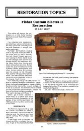
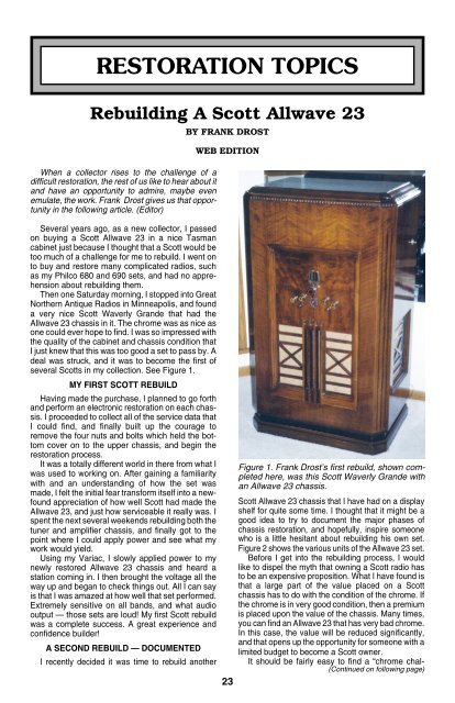
Figure 1. Frank Drost’s first rebuild, shown completed<br />
here, was this <strong>Scott</strong> Waverly Grande with<br />
an <strong>Allwave</strong> <strong>23</strong> chassis.<br />
<strong>Scott</strong> <strong>Allwave</strong> <strong>23</strong> chassis that I have had on a display<br />
shelf for quite some time. I thought that it might be a<br />
good idea to try to document the major phases of<br />
chassis restoration, and hopefully, inspire someone<br />
who is a little hesitant about rebuilding his own set.<br />
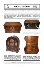
Figure 2 shows the various units of the <strong>Allwave</strong> <strong>23</strong> set.<br />
Before I get into the rebuilding process, I would<br />
like to dispel the myth that owning a <strong>Scott</strong> radio has<br />
to be an expensive proposition. What I have found is<br />
that a large part of the value placed on a <strong>Scott</strong><br />
chassis has to do with the condition of the chrome. If<br />
the chrome is in very good condition, then a premium<br />
is placed upon the value of the chassis. Many times,<br />
you can find an <strong>Allwave</strong> <strong>23</strong> that has very bad chrome.<br />
In this case, the value will be reduced significantly,<br />
and that opens up the opportunity for someone with a<br />
limited budget to become a <strong>Scott</strong> owner.<br />
It should be fairly easy to find a “chrome chal-<br />
(Continued on following page)
(<strong>Scott</strong> <strong>Allwave</strong> <strong>23</strong>, continued)<br />
lenged” <strong>Allwave</strong> <strong>23</strong> upper and lower<br />
chassis and speaker for under<br />
$1,000. How much under that figure<br />
would depend upon just how<br />
bad the chrome might be. A rusty<br />
set of chassis will sell well under<br />
that price. The important thing is<br />
to inspect the undersides of the<br />
chassis you are buying, and make<br />
sure they are clean and complete.<br />
And remember, the condition of<br />
the chrome will not affect the way<br />
the set will perform. You can enjoy<br />
<strong>Scott</strong> performance for less, if<br />
you are willing to accept flaws in<br />
appearance.<br />
BEGINNING THE REBUILD<br />
The first thing you should do is<br />
get a copy of the service information<br />
found in Rider’s Volume 14.<br />
You will find the schematic diagram,<br />
parts location and description,<br />
and other information that will<br />
answer questions that will come<br />
up during the rebuilding process.<br />
Have a notebook ready, and make<br />
thorough notes of each stage of<br />
disassembly. You will need to refer<br />
to it later on when it’s time to<br />
put things back together.<br />
Now let’s start with the upper<br />
chassis. I would suggest taking a<br />
quick look at the service info to get<br />
somewhat familiarized with how<br />
the set is constructed. Start the<br />
project by removing all of the tube<br />
shields and tubes. Next remove<br />
the remaining seven circular<br />
chrome cans by slightly rocking<br />
and pulling them up from the chassis.<br />
The back four cans will have a<br />
grid cap lead coming from them.<br />
Cut the lead off and then remove<br />
the can. Replace the leads with<br />
new wire, as the old wire will probably<br />
have failing insulation on it.<br />
Alternatively, you may decide<br />
to leave the four IF cans on the<br />
chassis until it is time to replace<br />
parts in each assembly in order to<br />
protect the delicate IF transformers.<br />
You can decide which way<br />
you prefer to proceed. Then set<br />
the removed parts aside for cleaning.<br />
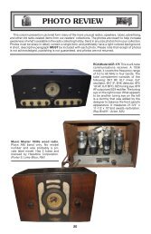
Figure 3 shows the upper<br />
chassis with the tubes and chrome<br />
cans removed.<br />
Remove the bottom cover. You<br />
will see a second metal cover that<br />
protects a disk with coils mounted<br />
to it. This disk contains the RF<br />
and oscillator coils for each band,<br />
and rotates into proper position as the band switch<br />
is turned. Remove this metal cover by unscrewing<br />
the flat head screws on the front and rear of the<br />
chassis that hold it on. The exposed disk-mounted<br />
Figure 2. The various component parts of the <strong>Allwave</strong> <strong>23</strong> set.<br />
Figure 3. A top view of the upper chassis with tube and coil shields<br />
removed..<br />
Figure 4. A bottom view of the upper chassis showing the rotating coil disk.<br />
24<br />
coils are shown in Figure 4. Once this is removed,<br />
proceed to remove the circular disk with coils by<br />
removing the center nuts. There will be two of them,<br />
(Continued on following page)
one on top of the other. Figure 5<br />
shows a view of the chassis with<br />
the coil assembly removed.<br />
Don’t worry about locking the<br />
band selector assembly in place,<br />
because disk replacement is very<br />
simple. The service data explains<br />
how to orient the disk to proper<br />
positioning, and it is a simple matter<br />
of just replacing the two nuts<br />
which hold the disk in place. Once<br />
you remove the disk, you will notice<br />
two button-shaped metal objects<br />
that have some spring action.<br />
They serve the purpose of<br />
locking the disk into position. You<br />
can remove them one at a time for<br />
cleaning and lubrication. Once<br />
you’ve done that, place tape over<br />
each one so that they do not fall<br />
out and get lost as you move the<br />
chassis around.<br />
After you have removed the disk coil assembly,<br />
you can now access and remove the screws that<br />
hold the two chrome boxes found on the top front of<br />
the chassis. The large box covers the tuning capacitor,<br />
and the smaller one covers a coil assembly.<br />
Look for large flat blade screws located under each<br />
box.<br />
In the case of the tuning capacitor cover, you will<br />
probably end up removing some of the screws which<br />
hold the tuning capacitor to the chassis, as well as<br />
those which hold the cover. This is because they are<br />
right next to each other and a little hard to tell which<br />
hold down what. That’s okay, because I always<br />
remove the tuning capacitor anyway, as it makes<br />
cleaning the chassis a lot easier.<br />
Make sure the tuning capacitor is fully closed for<br />
clearance when removing the cover. Make some<br />
notes on where the tuning capacitor wires connect,<br />
and then cut them to free the part. The coil cover will<br />
have a 2-lug terminal strip mounted to it. The tuning<br />
meter connects here, and it is held on by one screw.<br />
Remove this strip to free the coil cover. You can also<br />
remove the tuning meter from the chassis by removing<br />
the one screw holding it to the chassis.<br />
At this point, you now have the chassis stripped<br />
for cleaning, and best accessibility for parts replacement.<br />
Now is the time to wash and polish all of the<br />
tube shields, cans, and chrome boxes, as well as<br />
clean and polish the upper side of the chassis. Be<br />
careful not to damage any of the exposed coils,<br />
especially the four IF coils at the rear of the chassis.<br />
Now would be a good time to check for open coils<br />
and bad audio transformer windings. Refer to the<br />
service info to identify each coil and winding connections<br />
for testing. The IF coils usually show around<br />
11 ohms on each side. Be sure to check the audio<br />
transformer, which is the large square black box<br />
found on top of the chassis. It has five leads that<br />
protrude through the chassis. They are color coded,<br />
and there is normally enough color left for identifying<br />
the windings to be paired during your check. This<br />
part is somewhat prone to failure, and it is wise to<br />
know ahead of time whether you need to locate a<br />
replacement or not.<br />
One thing should be obvious by now. There is a<br />
lot of room to work in under the chassis. If you are<br />
Figure 5. A bottom view of the upper chassis with the rotating coil disk<br />
removed.<br />
25<br />
rebuilding a set that has never been worked on<br />
before, replacing the wax capacitors will go quickly.<br />
They are clearly marked, and easy to get at. I have<br />
found that most of the resistors will be in spec, and<br />
the cloth wiring seems to hold up better than other<br />
brands from the same era.<br />
Much of the rebuild will be just like any other set<br />
you have worked on. So rather than describe every<br />
step of the rebuilding process, I will focus on what is<br />
different about the <strong>Scott</strong>.<br />
RUBBER WIRE REPLACEMENT.<br />
Generally speaking, the cloth-covered wire found<br />
in the <strong>Allwave</strong> <strong>23</strong> should be in excellent condition<br />
and not need replacement. <strong>Scott</strong> did use a limited<br />
amount of rubber-insulated wire in the signal path,<br />
which sometimes is found to be in a hard, brittle<br />
state. The insulation flakes off causing shorts to<br />
chassis. Sometimes these shorts are hard to spot,<br />
and makes troubleshooting difficult.<br />
The best thing to do is to inspect all of the rubber<br />
wire runs for insulation failures, and replace those<br />
that are bad. Make sure that the replaced wires run<br />
exactly the way the old ones did. It makes a lot of<br />
sense to replace the grid cap connecting wires that<br />
exit the IF cans with new black insulated wire. You<br />
can do this just before replacing the chrome cans<br />
which cover each IF transformer assembly.<br />
Finally, pay close attention to the rubber wires<br />
that run on top of the chassis. Many run through pilot<br />
holes, and some have the chrome cover cans in<br />
contact with them. This is where shorts can occur if<br />
the insulation fails. Take the necessary action to<br />
ensure that no shorting can occur.<br />
REBUILDING THE CHOKE ASSEMBLIES.<br />
There are three square cans mounted underneath<br />
the chassis that contain the IF diode choke<br />
assembly, RF diode choke assembly, and RF choke<br />
assembly. Each assembly is identified in the service<br />
info along with an internal component description. In<br />
order to service these assemblies, they must be<br />
removed from the chassis.<br />
Before removal, it will help to make a drawing of<br />
where the wires go so as to avoid any confusion<br />
upon reinstallation. After you have completed your<br />
(Continued on following page)
(<strong>Scott</strong> <strong>Allwave</strong> <strong>23</strong>, continued)<br />
drawing, you can then carefully unsolder each lead<br />
and remove the fasteners that hold the assembly to<br />
the chassis. Just do one assembly at a time to keep<br />
things under control.<br />
Each assembly will contain a coil and various<br />
resistors and capacitors. Each one has a wax capacitor<br />
that should be replaced, and there will also<br />
be resistors that should be inspected and replaced if<br />
necessary. I cannot emphasize enough how delicate<br />
these assemblies are.<br />
I would advise against removing the coils from<br />
the can. There is a chance that you might flex things<br />
enough to cause one of the fine coil wires to break,<br />
and then you would know what trouble really is! I<br />
normally clip the part that I want to replace and<br />
leave the lead to use as a mount. Then I wind the<br />
lead of the new part into a small coil and slip it over<br />
the old lead and solder it. That way, you can replace<br />
the part with minimal chance of damage to the coil.<br />
I have yet to have problems with any of the mica<br />
capacitors that are part of the assembly, and just<br />
leave them as they are. Replacement would require<br />
total disassembly to get at the mica capacitor and<br />
it’s not worth taking the chance.<br />
Slip any insulating covers back onto the replaced<br />
parts and install the assembly using the notes you<br />
made earlier. This is definitely one of the most<br />
tedious parts of rebuilding the <strong>Scott</strong> <strong>Allwave</strong> <strong>23</strong>, and<br />
I suggest that you allow as much time for this as you<br />
need.<br />
IF SECTION PARTS REPLACEMENT<br />
The <strong>Allwave</strong> <strong>23</strong> has four IF stages that are physically<br />
located along the back of the chassis. The<br />
<strong>Scott</strong> IF transformers are much larger than what you<br />
usually see in a radio of that era, and use large air<br />
trimmer capacitors instead of the common ceramic/<br />
mica type. Each IF transformer and its associated<br />
parts are housed inside of a chrome can. A grid lead<br />
wire exits the upper side of each can.<br />
There are two capacitors to replace in each assembly<br />
and two resistors to check for proper value.<br />
The first IF stage also has a 2-meg resistor and a<br />
mica capacitor. The important thing to remember<br />
when working on each IF assembly is to be very<br />
careful of the exposed windings on each IF transformer.<br />
Although they are constructed very well,<br />
movement of the chassis while the coils are exposed,<br />
or a misdirected soldering iron can damage<br />
a coil. Replacements would have to come from<br />
another <strong>Allwave</strong> <strong>23</strong> chassis, so that would make it a<br />
difficult and expensive proposition.<br />
My procedure is to do one IF section at a time.<br />
Make notes regarding parts and wiring connections,<br />
and then carefully replace each capacitor and any<br />
bad resistors. Each capacitor fits through a hole in<br />
the chassis.<br />
I have found that it makes sense to cut the ground<br />
lead from each capacitor as close to the old part as<br />
possible. Then fit the new capacitor through the hole<br />
to where it is about half way through. Then make a<br />
connection from the existing cut ground wire to the<br />
new part. This keeps the unusually long ground run<br />
as it was originally done. You will probably have to<br />
extend the leads from the new parts to their connecting<br />
point. Try to position the run like the original.<br />
You can use some insulation slipped over the extended<br />
lead to protect against a potential short.<br />
26<br />
There are some rubber wires that connect from<br />
the air trimmer capacitors to the underside of the<br />
chassis. You will notice that some of these wires<br />
terminate in what makes up part of the variable<br />
selectivity sections.<br />
There are four square-shaped cans under the<br />
chassis that run in a straight line with a shaft going<br />
through them. Remove each can to access what<br />
resembles a truncated variable tuning capacitor.<br />
Looking closely, you can see points where the wires<br />
from above the chassis will connect. If these wires in<br />
your set are in good condition, it would be best to<br />
just leave them as they are. But if the insulation is<br />
crumbling, then replacement will be necessary.<br />
Carefully heat the termination point at the variable<br />
selectivity section with your soldering iron while<br />
pulling slightly on the wire from the top of the chassis.<br />
The wire will come out. I usually heat that<br />
connecting spot again, and clean out any remaining<br />
solder until the hole for the wire is fully open. This<br />
makes installation of the new wire possible. Cut<br />
your new wires exactly the same length, and then<br />
install and solder.<br />
The covers can be reinstalled once the wires have<br />
been checked or replaced. If you decide to align the<br />
set after you have completed the rebuilding process,<br />
then each cover will have to be removed in order to<br />
access each air trimmer adjuster. My suggestion is<br />
to replace the covers and see how the set performs<br />
before assuming that an alignment is necessary.<br />
Finally, install a new grid wire making it long enough<br />
to exit through the hole in the chrome can. Position<br />
the chrome can to the chassis, and then trim the wire<br />
to a correct length and solder the grid cap to it.<br />
REASSEMBLY<br />
Once you have performed the above procedures,<br />
replaced all of the remaining wax capacitors and<br />
any other parts that were found to be bad, the<br />
chassis is ready for reassembly.<br />
Start by replacing the tuning capacitor and both<br />
chrome boxes that are located on the top front of the<br />
chassis. Installation of the tuning capacitor is fairly<br />
straightforward. It might be easier to connect new<br />
wires to the part before installing it to the chassis.<br />
Feed the new wires through any chassis holes, and<br />
attach the tuning condenser to the chassis. Then<br />
connect the new wires to their appropriate connecting<br />
points.<br />
Again make sure that the tuning capacitor is fully<br />
closed, then replace the chrome cover on the chassis.<br />
Replace the other square chrome can over the<br />
coil. At this point, you should see a huge increase in<br />
chassis weight. Continue replacing the remaining<br />
parts and chrome can covers by referring to the<br />
notes you have made during the disassembly process.<br />
When you have reached the point where it is time<br />
to replace the disk coil assembly, refer to the Rider’s<br />
service manual for specific instructions on how to<br />
orient the disk for proper installation. Install both<br />
nuts and washers. Check for proper operation by<br />
rotating the band switch throughout all four positions.<br />
After you have installed the disk, then you can<br />
replace the metal cover which will protect it from<br />
damage.<br />
Continue on with final assembly, but leave the<br />
bottom cover off so that you will be able to make<br />
voltage checks during your testing process.
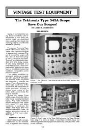
Figure 6. The completely restored <strong>Allwave</strong> <strong>23</strong> on the workbench for testing. Left to right, the speaker<br />
with an optional diffuser, the power amplifier/power supply, and the main chassis.<br />
POWER SUPPLY/AMPLIFIER<br />
The second chassis is the actual power supply<br />
and final amplifier for the <strong>Allwave</strong> <strong>23</strong>. There is little<br />
that is unusual going on here, and it is mostly a<br />
matter of replacing the electrolytic and paper capacitors,<br />
and any out-of-spec resistors. Most power<br />
cords on these <strong>Scott</strong>s are usually in bad shape, so<br />
make sure that you replace the power cord and<br />
wires going to the on/off switch.<br />
There are variations of these chassis that seem<br />
to depend upon when they were manufactured. It is<br />
helpful to compare your chassis to the service info to<br />
see which one you have. I have even seen hybrid<br />
versions where there is some overlap between both<br />
types. Spending time up front to determine what you<br />
have will save a lot of time later on when you start to<br />
do the actual repair work.<br />
INITIAL START UP AND TEST<br />
Once both chassis have been restored, it is<br />
time to connect them up with each other and the<br />
speaker. Figure 6 shows the completed set on the<br />
work bench for testing. Refer to the service instructions<br />
once again and look for the info on<br />
speaker connections.<br />
<strong>Scott</strong> offered a pair of tweeters for this set. They<br />
were optional, and not all buyers ordered them.<br />
Because of this, you need to pay attention to how<br />
the short cord that is part of the loud speaker is<br />
plugged in to the sockets located at the speaker<br />
base. It must be correctly oriented depending upon<br />
whether you have tweeters or not. If it is improperly<br />
installed, then you will damage your set. Before<br />
applying any power to the set, make sure you have<br />
that plug properly connected.<br />
Attach your antenna following the instructions in<br />
the service info for long wire antenna set up. Set the<br />
controls in preparation for power up. Turn to the AM<br />
band, and set the sensitivity control for maximum.<br />
Set the selectivity/fidelity control somewhere be-<br />
27<br />
tween “sharp” and the middle of its range.<br />
Using a variac, slowly bring the set up to power in<br />
stages, and watch for anything unusual which might<br />
be happening. You should notice some audio coming<br />
forth. Once you do, tune the set for a station.<br />
Continue to ramp up the variac until you finally are at<br />
normal line voltage.<br />
At this point I am assuming that your time and<br />
patience has paid off, and you are hearing a station<br />
coming in loud and clear! It is now time to experiment<br />
with the set and see how it performs on all<br />
bands, as well as how each control is functioning. I<br />
would advise performing voltage checks on each<br />
chassis as a quality control step in ensuring that the<br />
set will operate as the designers intended.<br />
I have rebuilt several <strong>Allwave</strong> <strong>23</strong> sets, and each<br />
one has held its alignment surprisingly well. If you<br />
decide to align yours, the information for this process<br />
is in the service documentation.<br />
SUMMARY<br />
A <strong>Scott</strong> <strong>Allwave</strong> <strong>23</strong> is a classic radio that can be<br />
attainable by most radio collectors. As I have found,<br />
they are not beyond the scope of most hobbyists<br />
who have had some prior experience with radio<br />
restoration. These were expensive, quality radios<br />
when new, and their survival rate seems to be quite<br />
high. They are out there. Good luck on your search<br />
and restoration of your own <strong>Scott</strong>!<br />
References:<br />
Rider, John F. Trouble Shooter’s Manual, Vol, 14.<br />
Jesperson, Alan. Great Northern Vintage <strong>Radio</strong>,<br />
P.O. Box 17338, Minneapolis, MN 55417. 612-<br />
727-2489. www.gn4radios.com.<br />
Frank Drost, a computer programmer, enjoys restoring<br />
large, high-end, 1930s-1940s console radios.<br />
Currently, the core of his collection consists of<br />
several <strong>Scott</strong> Imperials and Philharmonic, along with<br />
variants of late 1930s 15-tube Zeniths.