R&S®ZVA Vector Network Analyzer Specifications
R&S®ZVA Vector Network Analyzer Specifications
R&S®ZVA Vector Network Analyzer Specifications

Create successful ePaper yourself
Turn your PDF publications into a flip-book with our unique Google optimized e-Paper software.
R&<strong>S®ZVA</strong><br />
<strong>Vector</strong> <strong>Network</strong><br />
<strong>Analyzer</strong><br />
<strong>Specifications</strong><br />
Test & Measurement<br />
Data Sheet | 06.00
Version 06.00, July 2009<br />
CONTENTS<br />
Measurement range ........................................................................................................................................................ 3<br />
Measurement speed........................................................................................................................................................ 7<br />
Measurement accuracy .................................................................................................................................................. 9<br />
Effective system data ................................................................................................................................................... 18<br />
Test port output ............................................................................................................................................................ 20<br />
Test port input............................................................................................................................................................... 24<br />
Additional front panel connectors............................................................................................................................... 28<br />
Optional front panel connectors.................................................................................................................................. 28<br />
Display ........................................................................................................................................................................... 28<br />
Rear panel connectors ................................................................................................................................................. 28<br />
Options .......................................................................................................................................................................... 30<br />
General data .................................................................................................................................................................. 34<br />
Ordering information .................................................................................................................................................... 35<br />
2 Rohde & Schwarz R&S ® ZVA <strong>Vector</strong> <strong>Network</strong> <strong>Analyzer</strong>
Version 06.00, July 2009<br />
<strong>Specifications</strong> are valid under the following conditions:<br />
90 minutes warm-up time at ambient temperature, specified environmental conditions met, calibration cycle adhered to, and all internal<br />
adjustments performed. Data designated „overrange“ and data without tolerance limits is not binding. Unless otherwise stated,<br />
specifications apply to test ports and a nominal source power of –10 dBm.<br />
Measurement range<br />
Impedance<br />
50 Ω<br />
Test port connector<br />
R&S ® ZVA8<br />
type N, female<br />
R&S ® ZVA24<br />
3.5 mm, male<br />
R&S ® ZVA40<br />
2.92 mm, male<br />
R&S ® ZVA40<br />
2.4 mm, male<br />
R&S ® ZVA50<br />
2.4 mm, male<br />
R&S ® ZVA67<br />
1.85 mm, male<br />
Number of test ports 2 or 4<br />
Frequency range<br />
R&S ® ZVA8<br />
300 kHz to 8 GHz<br />
R&S ® ZVA24<br />
10 MHz to 24 GHz<br />
R&S ® ZVA40<br />
10 MHz to 40 GHz<br />
R&S ® ZVA50<br />
10 MHz to 50 GHz<br />
R&S ® ZVA67<br />
10 MHz to 67 GHz<br />
Static frequency accuracy<br />
without optional oven quartz 8×10 –6<br />
with optional oven quartz 1×10 –7<br />
Frequency resolution<br />
1 Hz<br />
Number of measurement points user-selectable 1 to 60001<br />
Measurement bandwidths 1/2/5 steps 1 Hz to 1 MHz<br />
Dynamic range of the R&S ® ZVA8<br />
(without optional step attenuators<br />
and without optional direct<br />
from PORT 1 to PORT 2 and<br />
from PORT 3 to PORT 4<br />
300 kHz to 50 MHz >100 dB, typ. 110 dB<br />
generator/receiver access)<br />
50 MHz to 100 MHz >120 dB, typ. 130 dB<br />
100 MHz to 4 GHz >130 dB, typ. 140 dB<br />
4 GHz to 7 GHz >125 dB, typ. 135 dB<br />
Dynamic range of the R&S ® ZVA24<br />
(without optional step attenuators<br />
and without optional direct<br />
generator/receiver access)<br />
Dynamic range of the R&S ® ZVA40<br />
(without optional step attenuators<br />
and without optional direct<br />
generator/receiver access)<br />
Dynamic range of the R&S ® ZVA50<br />
(without optional step attenuators<br />
and without optional direct<br />
generator/receiver access)<br />
7 GHz to 8 GHz >120 dB, typ. 130 dB<br />
from PORT 1 to PORT 2 and<br />
from PORT 3 to PORT 4<br />
10 MHz to 100 MHz >90 dB, typ. 105 dB<br />
100 MHz to 700 MHz >105 dB, typ. 120 dB<br />
700 MHz to 2 GHz >125 dB, typ. 130 dB<br />
2 GHz to 13 GHz >130 dB, typ. 135 dB<br />
13 GHz to 24 GHz >125 dB, typ. 130 dB<br />
from PORT 1 to PORT 2 and<br />
from PORT 3 to PORT 4<br />
10 MHz to 50 MHz >90 dB, typ. 100 dB<br />
50 MHz to 500 MHz >105 dB, typ. 115 dB<br />
500 MHz to 2 GHz >125 dB, typ. 135 dB<br />
2 GHz to 20 GHz >130 dB, typ. 140 dB<br />
20 GHz to 24 GHz >125 dB, typ. 135 dB<br />
24 GHz to 32 GHz >115 dB, typ. 125 dB<br />
32 GHz to 40 GHz >110 dB, typ. 115 dB<br />
from PORT 1 to PORT 2 and<br />
from PORT 3 to PORT 4<br />
10 MHz to 50 MHz >90 dB, typ. 100 dB<br />
50 MHz to 500 MHz >105 dB, typ. 115 dB<br />
500 MHz to 2 GHz >125 dB, typ. 135 dB<br />
2 GHz to 20 GHz >130 dB, typ. 140 dB<br />
20 GHz to 24 GHz >125 dB, typ. 135 dB<br />
24 GHz to 32 GHz >120 dB, typ. 130 dB<br />
32 GHz to 40 GHz >115 dB, typ. 125 dB<br />
40 GHz to 50 GHz >110 dB, typ. 120 dB<br />
Rohde & Schwarz R&S ® ZVA <strong>Vector</strong> <strong>Network</strong> <strong>Analyzer</strong> 3
Version 06.00, July 2009<br />
Dynamic range of the R&S ® ZVA67<br />
(without optional step attenuators<br />
and without optional direct<br />
generator/receiver access)<br />
from PORT 1 to PORT 2<br />
10 MHz to 50 MHz >70 dB, typ. 90 dB<br />
50 MHz to 500 MHz >100 dB, typ. 115 dB<br />
500 MHz to 2 GHz >115 dB, typ. 125 dB<br />
2 GHz to 24 GHz >125 dB, typ. 135 dB<br />
24 GHz to 32 GHz >120 dB, typ. 130 dB<br />
32 GHz to 40 GHz >115 dB, typ. 125 dB<br />
40 GHz to 50 GHz >110 dB, typ. 120 dB<br />
50 GHz to 65 GHz >107 dB, typ. 115 dB<br />
65 GHz to 67 GHz >100 dB, typ. 110 dB<br />
67 GHz to 70 GHz typ. 103 dB<br />
The dynamic range is defined as the difference between the actually available maximum source power and the rms value of the data<br />
trace of the transmission magnitude, which is produced by noise and crosstalk with the test ports short-circuited. The specification is<br />
valid without system error correction and at 10 Hz measurement bandwidth. The dynamic range can be increased by using a<br />
measurement bandwidth of 1 Hz. At single frequencies below 100 MHz, the dynamic range can be affected by spurious signals.<br />
Dynamic range at optional measurement<br />
input (direct generator/receiver access<br />
option) of the R&S ® ZVA8<br />
Dynamic range at optional measurement<br />
input (direct generator/receiver access<br />
option) of the R&S ® ZVA24<br />
Dynamic range at optional measurement<br />
input (direct generator/receiver access<br />
option) of the R&S ® ZVA40<br />
Dynamic range at optional measurement<br />
input (direct generator/receiver access<br />
option) of the R&S ® ZVA50<br />
Dynamic range at optional measurement<br />
input (direct generator/receiver access<br />
option) of the R&S ® ZVA67<br />
from PORT 1 to MEAS 2 IN<br />
300 kHz to 10 MHz typ. >125 dB<br />
10 MHz to 100 MHz typ. >135 dB<br />
100 MHz to 8 GHz typ. >145 dB<br />
from PORT 1 to MEAS 2 IN<br />
10 MHz to 100 MHz typ. >135 dB<br />
100 MHz to 13 GHz typ. >145 dB<br />
13 GHz to 20 GHz typ. >140 dB<br />
20 GHz to 24 GHz typ. >130 dB<br />
from PORT 1 to MEAS 2 IN<br />
10 MHz to 100 MHz typ. >140 dB<br />
100 MHz to 20 GHz typ. >150 dB<br />
20 GHz to 24 GHz typ. >140 dB<br />
24 GHz to 32 GHz typ. >130 dB<br />
32 GHz to 40 GHz typ. >120 dB<br />
from PORT 1 to MEAS 2 IN<br />
10 MHz to 100 MHz typ. >140 dB<br />
100 MHz to 20 GHz typ. >150 dB<br />
20 GHz to 24 GHz typ. >145 dB<br />
24 GHz to 32 GHz typ. >140 dB<br />
32 GHz to 40 GHz typ. >135 dB<br />
40 GHz to 50 GHz typ. >130 dB<br />
from PORT 1 to MEAS 2 IN<br />
10 MHz to 100 MHz typ. >140 dB<br />
100 MHz to 20 GHz typ. >145 dB<br />
20 GHz to 24 GHz typ. >145 dB<br />
24 GHz to 32 GHz typ. >140 dB<br />
32 GHz to 40 GHz typ. >135 dB<br />
40 GHz to 50 GHz typ. >130 dB<br />
50 GHz to 67 GHz typ. >125 dB<br />
4 Rohde & Schwarz R&S ® ZVA <strong>Vector</strong> <strong>Network</strong> <strong>Analyzer</strong>
Version 06.00, July 2009<br />
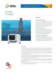
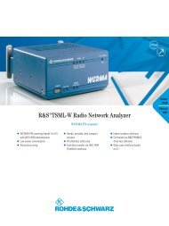
Diagram: Dynamic range in dB versus frequency in GHz of the R&S ® ZVA8<br />
Diagram: Dynamic range in dB versus frequency in GHz of the R&S ® ZVA24<br />
Diagram: Dynamic range in dB versus frequency in GHz of the R&S ® ZVA40<br />
Rohde & Schwarz R&S ® ZVA <strong>Vector</strong> <strong>Network</strong> <strong>Analyzer</strong> 5
Version 06.00, July 2009<br />
Diagram: Dynamic range in dB versus frequency in GHz of the R&S ® ZVA50<br />
Diagram: Dynamic range in dB versus frequency in GHz of the R&S ® ZVA67<br />
6 Rohde & Schwarz R&S ® ZVA <strong>Vector</strong> <strong>Network</strong> <strong>Analyzer</strong>
Version 06.00, July 2009<br />
Measurement speed<br />
Measurement time per point<br />
CW mode,<br />
1 MHz measurement bandwidth
Version 06.00, July 2009<br />
Sweep times of the R&S ® ZVA67<br />
Sweep times depend on the number of measurement points, the measurement bandwidth, and the start and stop frequencies.<br />
They include times for retrace and internal band switching and are valid with ALC and display switched off.<br />
Number of measurement points 51 101 201 401 801 1601<br />
R&S ® ZVA67 with start frequency 6 GHz, stop frequency 12 GHz<br />
For a measurement bandwidth of 100 kHz<br />
With full one-port calibration or<br />
with correction switched off 1.8 ms 3 ms 6 ms 11 ms 22 ms 42 ms<br />
With TOSM calibration 3 ms 6 ms 11 ms 21 ms 41 ms 116 ms<br />
For a measurement bandwidth of 1 MHz<br />
With full one-port calibration or<br />
with correction switched off 1.2 ms 2 ms 4 ms 7 ms 14 ms 25 ms<br />
With TOSM calibration 2 ms 4 ms 7 ms 13 ms 25 ms 84 ms<br />
R&S ® ZVA67 with start frequency 10 MHz and stop frequency 67 GHz<br />
For a measurement bandwidth of 100 kHz<br />
With full one-port calibration or<br />
with correction switched off 2.8 ms 4 ms 7 ms 12 ms 23 ms 42 ms<br />
With TOSM calibration 4.1 ms 7 ms 12 ms 22 ms 42 ms 116 ms<br />
For a measurement bandwidth of 1 MHz<br />
With full one-port calibration or<br />
with correction switched off 2.2 ms 3 ms 4.6 ms 8 ms 14 ms 26 ms<br />
With TOSM calibration 3 ms 5 ms 8 ms 14 ms 26 ms 85 ms<br />
Table: Sweep times of the R&S ® ZVA67<br />
8 Rohde & Schwarz R&S ® ZVA <strong>Vector</strong> <strong>Network</strong> <strong>Analyzer</strong>
Version 06.00, July 2009<br />
Measurement accuracy<br />
This data is valid between +18 °C and +28 °C, provided the temperature has not varied by more than 1 K after calibration. Validity of<br />
the data is conditional on the use of a suitable calibration kit. This calibration kit is used to achieve the effective system data specified<br />
below. Frequency points, measurement bandwidth, and sweep time have to be identical for measurement and calibration (no<br />
interpolation allowed).<br />
Accuracy of transmission measurements<br />
R&S ® ZVA8<br />
300 kHz to 1 MHz for +15 dB to –45 dB
Version 06.00, July 2009<br />
R&S ® ZVA50<br />
10 MHz to 50 MHz for +15 dB to –30 dB
Version 06.00, July 2009<br />
R&S ® ZVA67<br />
10 MHz to 50 MHz for +15 dB to –30 dB
Version 06.00, July 2009<br />
Magnitude<br />
Phase<br />
Uncertainty / dB<br />
10<br />
1<br />
0.1<br />
0.01<br />
0 -20 -40 -60 -80<br />
Transmission coefficient / dB<br />
-100<br />
Uncertainty / deg<br />
100<br />
10<br />
1<br />
0.1<br />
0<br />
-20 -40 -60 -80<br />
Transmission coefficient / dB<br />
-100<br />
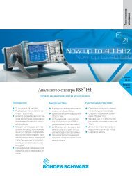
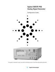
Diagram: Typical accuracy of transmission magnitude and transmission phase measurements of the R&S ® ZVA8<br />
in the frequency range 300 kHz to 50 MHz<br />
Magnitude<br />
Phase<br />
10<br />
100<br />
Uncertainty / dB<br />
1<br />
0.1<br />
Uncertainty / deg<br />
10<br />
1<br />
0.01<br />
0 -20 -40 -60 -80<br />
Transmission coefficient / dB<br />
-100<br />
0.1<br />
0<br />
-20 -40 -60 -80<br />
Transmission coefficient / dB<br />
-100<br />
Diagram: Typical accuracy of transmission magnitude and transmission phase measurements of the R&S ® ZVA8<br />
in the frequency range 50 MHz to 8 GHz<br />
12 Rohde & Schwarz R&S ® ZVA <strong>Vector</strong> <strong>Network</strong> <strong>Analyzer</strong>
Version 06.00, July 2009<br />
Magnitude<br />
Phase<br />
10<br />
100<br />
Uncertainty / dB<br />
1<br />
0.1<br />
Uncertainty / deg<br />
10<br />
1<br />
0.01<br />
0<br />
-20 -40 -60 -80<br />
Transmission coefficient / dB<br />
-100<br />
0.1<br />
0<br />
-20 -40 -60 -80<br />
Transmission coefficient / dB<br />
-100<br />
Diagram: Typical accuracy of transmission magnitude and transmission phase measurements of the R&S ® ZVA24<br />
in the frequency range 10 MHz to 700 MHz<br />
Magnitude<br />
Phase<br />
10<br />
100<br />
Uncertainty / dB<br />
1<br />
0.1<br />
Uncertainty / deg<br />
10<br />
1<br />
0.01<br />
0<br />
-20 -40 -60 -80<br />
Transmission coefficient / dB<br />
-100<br />
0.1<br />
0<br />
-20 -40 -60 -80<br />
Transmission coefficient / dB<br />
-100<br />
Diagram: Typical accuracy of transmission magnitude and transmission phase measurements of the R&S ® ZVA24<br />
in the frequency range 700 MHz to 24 GHz<br />
Rohde & Schwarz R&S ® ZVA <strong>Vector</strong> <strong>Network</strong> <strong>Analyzer</strong> 13
Version 06.00, July 2009<br />
Magnitude<br />
Phase<br />
10<br />
100<br />
Uncertainty / dB<br />
1<br />
0.1<br />
Uncertainty / deg<br />
10<br />
1<br />
0.01<br />
0<br />
-20 -40 -60 -80<br />
Transmission coefficient / dB<br />
-100<br />
0.1<br />
0<br />
-20 -40 -60 -80<br />
Transmission coefficient / dB<br />
-100<br />
Diagram: Typical accuracy of transmission magnitude and transmission phase measurements of the R&S ® ZVA40<br />
in the frequency range 10 MHz to 700 MHz<br />
Magnitude<br />
Phase<br />
Uncertainty / dB<br />
10<br />
1<br />
0.1<br />
0.01<br />
0<br />
-20 -40 -60 -80<br />
Transmission coefficient / dB<br />
-100<br />
Uncertainty / deg<br />
100<br />
10<br />
1<br />
0.1<br />
0<br />
-20 -40 -60 -80<br />
Transmission coefficient / dB<br />
-100<br />
Diagram: Typical accuracy of transmission magnitude and transmission phase measurements of the R&S ® ZVA40<br />
in the frequency range 700 MHz to 24 GHz<br />
Magnitude<br />
Phase<br />
Uncertainty / dB<br />
10<br />
1<br />
0.1<br />
0.01<br />
0<br />
-20 -40 -60 -80<br />
Transmission coefficient / dB<br />
-100<br />
Uncertainty / deg<br />
100<br />
10<br />
1<br />
0.1<br />
0<br />
-20 -40 -60 -80<br />
Transmission coefficient / dB<br />
-100<br />
Diagram: Typical accuracy of transmission magnitude and transmission phase measurements of the R&S ® ZVA40<br />
in the frequency range 24 GHz to 40 GHz<br />
14 Rohde & Schwarz R&S ® ZVA <strong>Vector</strong> <strong>Network</strong> <strong>Analyzer</strong>
Version 06.00, July 2009<br />
Magnitude<br />
Phase<br />
10<br />
100<br />
Uncertainty / dB<br />
1<br />
0.1<br />
Uncertainty / deg<br />
10<br />
1<br />
0.01<br />
0<br />
-20 -40 -60 -80<br />
Transmission coefficient / dB<br />
-100<br />
0.1<br />
0<br />
-20 -40 -60 -80<br />
Transmission coefficient / dB<br />
-100<br />
Diagram: Typical accuracy of transmission magnitude and transmission phase measurements of the R&S ® ZVA50 and of the<br />
R&S ® ZVA67<br />
in the frequency range 10 MHz to 700 MHz<br />
Magnitude<br />
Phase<br />
Uncertainty / dB<br />
10<br />
1<br />
0.1<br />
0.01<br />
0<br />
-20 -40 -60 -80<br />
Transmission coefficient / dB<br />
-100<br />
Uncertainty / deg<br />
100<br />
10<br />
1<br />
0.1<br />
0<br />
-20 -40 -60 -80<br />
Transmission coefficient / dB<br />
-100<br />
Diagram: Typical accuracy of transmission magnitude and transmission phase measurements of the R&S ® ZVA50 and of the<br />
R&S ® ZVA67<br />
in the frequency range 700 MHz to 24 GHz<br />
Magnitude<br />
Phase<br />
Uncertainty / dB<br />
10<br />
1<br />
0.1<br />
0.01<br />
0<br />
-20 -40 -60 -80<br />
Transmission coefficient / dB<br />
-100<br />
Uncertainty / deg<br />
100<br />
10<br />
1<br />
0.1<br />
0<br />
-20 -40 -60 -80<br />
Transmission coefficient / dB<br />
-100<br />
Diagram: Typical accuracy of transmission magnitude and transmission phase measurements of the R&S ® ZVA50 and of the<br />
R&S ® ZVA67<br />
in the frequency range 24 GHz to 50 GHz<br />
Rohde & Schwarz R&S ® ZVA <strong>Vector</strong> <strong>Network</strong> <strong>Analyzer</strong> 15
Version 06.00, July 2009<br />
Magnitude<br />
Phase<br />
10<br />
100<br />
Uncertainty / dB<br />
1<br />
0.1<br />
Uncertainty / deg<br />
10<br />
1<br />
0.01<br />
0<br />
-20 -40 -60 -80<br />
Transmission coefficient / dB<br />
-100<br />
0.1<br />
0<br />
-20 -40 -60 -80<br />
Transmission coefficient / dB<br />
-100<br />
Diagram: Typical accuracy of transmission magnitude and transmission phase measurements of the R&S ® ZVA67<br />
in the frequency range 50 GHz to 67 GHz<br />
16 Rohde & Schwarz R&S ® ZVA <strong>Vector</strong> <strong>Network</strong> <strong>Analyzer</strong>
Version 06.00, July 2009<br />
Accuracy of reflection measurements<br />
R&S ® ZVA8<br />
300 kHz to 1 MHz<br />
1 MHz to 8 GHz<br />
R&S ® ZVA24<br />
10 MHz to 50 MHz<br />
50 MHz to 24 GHz<br />
R&S ® ZVA40<br />
10 MHz to 50 MHz<br />
50 MHz to 40 GHz<br />
R&S ® ZVA50<br />
10 MHz to 50 MHz<br />
50 MHz to 50 GHz<br />
for +10 dB to –25 dB
Version 06.00, July 2009<br />
Effective system data<br />
This data is valid between +18 °C and +28 °C, provided the temperature has not varied by more than 1 K after calibration. The data is<br />
based on a measurement bandwidth of 10 Hz and system error calibration by means of a suitable calibration kit. Frequency points,<br />
measurement bandwidth, and sweep time have to be identical for measurement and calibration (no interpolation allowed).<br />
R&S ® ZVA8<br />
Directivity<br />
Source match<br />
Reflection tracking<br />
Load match<br />
Transmission tracking<br />
R&S ® ZVA24<br />
Directivity<br />
Source match<br />
Reflection tracking<br />
Load match<br />
Transmission tracking<br />
R&S ® ZVA40<br />
Directivity<br />
Source match<br />
Reflection tracking<br />
Load match<br />
Transmission tracking<br />
R&S ® ZVA50<br />
Directivity<br />
Source match<br />
Reflection tracking<br />
Load match<br />
Transmission tracking<br />
1 MHz to 4 GHz >46 dB, typ. 50 dB<br />
4 GHz to 8 GHz >40 dB, typ. 50 dB<br />
1 MHz to 4 GHz >40 dB, typ. 46 dB<br />
4 GHz to 8 GHz >36 dB, typ. 40 dB<br />
1 MHz to 4 GHz 40 dB, typ. 46 dB<br />
1 MHz to 4 GHz 40 dB, typ. 50 dB<br />
10 MHz to 700 MHz >30 dB, typ. 48 dB<br />
700 MHz to 24 GHz >30 dB, typ. 48 dB<br />
10 MHz to 700 MHz 40 dB, typ. 50 dB<br />
10 MHz to 700 MHz 36 dB, typ. 46 dB<br />
24 GHz to 40 GHz >30 dB, typ. 40 dB<br />
10 MHz to 700 MHz >30 dB, typ. 36 dB<br />
700 MHz to 24 GHz >30 dB, typ. 40 dB<br />
24 GHz to 40 GHz >30 dB, typ. 36 dB<br />
10 MHz to 700 MHz 32 dB, typ. 40 dB<br />
10 MHz to 700 MHz 30 dB, typ. 40 dB<br />
10 MHz to 700 MHz >30 dB, typ. 36 dB<br />
700 MHz to 24 GHz >30 dB, typ. 40 dB<br />
24 GHz to 50 GHz >30 dB, typ. 36 dB<br />
10 MHz to 700 MHz 32 dB, typ. 40 dB<br />
10 MHz to 700 MHz
Version 06.00, July 2009<br />
R&S ® ZVA67<br />
Directivity<br />
Source match<br />
Reflection tracking<br />
Load match<br />
Transmission tracking<br />
10 MHz to 700 MHz >30 dB, typ. 40 dB<br />
700 MHz to 24 GHz >36 dB, typ. 46 dB<br />
24 GHz to 40 GHz >30 dB, typ. 40 dB<br />
40 GHz to 67 GHz >26 dB, typ. 36 dB<br />
10 MHz to 700 MHz >30 dB, typ. 36 dB<br />
700 MHz to 24 GHz >30 dB, typ. 40 dB<br />
24 GHz to 40 GHz >30 dB, typ. 36 dB<br />
40 GHz to 67 GHz >26 dB, typ. 32 dB<br />
10 MHz to 700 MHz 28 dB, typ. 36 dB<br />
10 MHz to 700 MHz
Version 06.00, July 2009<br />
Test port output<br />
Power range<br />
(without optional step attenuators<br />
and without optional direct<br />
generator/receiver access)<br />
Power accuracy<br />
(with ALC on and<br />
without power calibration)<br />
Power linearity<br />
in temperature range +18 °C to +28 °C<br />
(with ALC on and<br />
without power calibration)<br />
Power resolution<br />
R&S ® ZVA8<br />
300 kHz to 50 MHz –40 dBm to +10 dBm, typ. –45 to +14 dBm<br />
50 MHz to 4 GHz –40 dBm to +13 dBm, typ. –45 to +15 dBm<br />
4 GHz to 7 GHz –40 dBm to +10 dBm, typ. –45 to +13 dBm<br />
7 GHz to 8 GHz –40 dBm to +8 dBm, typ. –45 to +12 dBm<br />
R&S ® ZVA24<br />
10 MHz to 13 GHz –30 dBm to +13 dBm, typ. –40 to +18 dBm<br />
13 GHz to 24 GHz –30 dBm to +10 dBm, typ. –40 to +16 dBm<br />
R&S ® ZVA40<br />
10 MHz to 50 MHz –30 dBm to +10 dBm, typ. –40 to +15 dBm<br />
50 MHz to 20 GHz –30 dBm to +13 dBm, typ. –40 to +18 dBm<br />
20 GHz to 32 GHz –30 dBm to +10 dBm, typ. –40 to +15 dBm<br />
32 GHz to 40 GHz –30 dBm to +6 dBm, typ. –40 to +12 dBm<br />
R&S ® ZVA50<br />
10 MHz to 50 MHz –30 dBm to +10 dBm, typ. –40 to +15 dBm<br />
50 MHz to 20 GHz –30 dBm to +13 dBm, typ. –40 to +18 dBm<br />
20 GHz to 32 GHz –30 dBm to +10 dBm, typ. –40 to +15 dBm<br />
32 GHz to 50 GHz –30 dBm to +6 dBm, typ. –40 to +12 dBm<br />
R&S ® ZVA67<br />
10 MHz to 50 MHz –30 dBm to +10 dBm, typ. –40 to +15 dBm<br />
50 MHz to 20 GHz –30 dBm to +13 dBm, typ. –40 to +18 dBm<br />
20 GHz to 32 GHz –30 dBm to +10 dBm, typ. –40 to +15 dBm<br />
32 GHz to 50 GHz –30 dBm to +6 dBm, typ. –40 to +12 dBm<br />
50 GHz to 67 GHz –30 dBm to +2 dBm, typ. –40 to +6 dBm<br />
67 GHz to 70 GHz typ. –30 to +2 dBm<br />
R&S ® ZVA8 at –10 dBm<br />
Version 06.00, July 2009<br />
Harmonics<br />
(output power referenced to maximum<br />
specified output power)<br />
R&S ® ZVA8<br />
300 kHz to 50 MHz at –3 dB typ.
Version 06.00, July 2009<br />
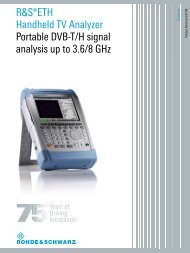
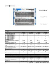
Diagram: Maximum output power in dBm versus frequency in GHz of the R&S ® ZVA40<br />
Diagram: Maximum output power in dBm versus frequency in GHz of the R&S ® ZVA50<br />
Diagram: Maximum output power in dBm versus frequency in GHz of the R&S ® ZVA67<br />
Diagram: Output power accuracy in dB versus frequency in GHz of the R&S ® ZVA8<br />
22 Rohde & Schwarz R&S ® ZVA <strong>Vector</strong> <strong>Network</strong> <strong>Analyzer</strong>
Version 06.00, July 2009<br />
Diagram: Output power accuracy in dB versus frequency in GHz of the R&S ® ZVA24<br />
Diagram: Output power accuracy in dB versus frequency in GHz of the R&S ® ZVA40<br />
Diagram: Output power accuracy in dB versus frequency in GHz of the R&S ® ZVA50<br />
Diagram: Output power accuracy in dB versus frequency in GHz of the R&S ® ZVA67<br />
Rohde & Schwarz R&S ® ZVA <strong>Vector</strong> <strong>Network</strong> <strong>Analyzer</strong> 23
Version 06.00, July 2009<br />
Test port input<br />
Match<br />
Maximum nominal input level<br />
without system error correction<br />
R&S ® ZVA8<br />
300 kHz to 7 GHz >16 dB<br />
7 GHz to 8 GHz >14 dB<br />
R&S ® ZVA24<br />
10 MHz to 50 MHz >10 dB<br />
50 MHz to 2 GHz >12 dB<br />
2 GHz to 24 GHz >8 dB<br />
R&S ® ZVA40<br />
10 MHz to 4 GHz >12 dB<br />
4 GHz to 20 GHz >8 dB<br />
20 GHz to 40 GHz >6 dB<br />
R&S ® ZVA50<br />
10 MHz to 50 MHz >8 dB<br />
50 MHz to 10 GHz >10 dB<br />
10 GHz to 20 GHz >8 dB<br />
20 GHz to 40 GHz >6 dB<br />
40 GHz to 50 GHz >5 dB<br />
R&S ® ZVA67<br />
10 MHz to 50 MHz >8 dB<br />
50 MHz to 10 GHz >10 dB<br />
10 GHz to 20 GHz >9 dB<br />
20 GHz to 40 GHz >8 dB<br />
40 GHz to 67 GHz >6 dB<br />
R&S ® ZVA8<br />
300 kHz to 8 GHz +13 dBm<br />
R&S ® ZVA24<br />
10 MHz to 13 GHz +15 dBm<br />
13 GHz to 24 GHz +10 dBm<br />
R&S ® ZVA40<br />
10 MHz to 13 GHz +10 dBm<br />
13 GHz to 24 GHz +6 dBm<br />
24 GHz to 40 GHz +3 dBm<br />
R&S ® ZVA50<br />
10 MHz to 13 GHz +10 dBm<br />
13 GHz to 24 GHz +6 dBm<br />
24 GHz to 50 GHz +3 dBm<br />
R&S ® ZVA67<br />
10 MHz to 13 GHz +10 dBm<br />
13 GHz to 24 GHz +6 dBm<br />
24 GHz to 67 GHz +3 dBm<br />
24 Rohde & Schwarz R&S ® ZVA <strong>Vector</strong> <strong>Network</strong> <strong>Analyzer</strong>
Version 06.00, July 2009<br />
Power measurement accuracy<br />
at –10 dBm without power calibration<br />
in temperature range 18 °C to 28 °C<br />
R&S ® ZVA8<br />
10 MHz to 8 GHz
Version 06.00, July 2009<br />
Receiver linearity<br />
Damage level<br />
Damage DC voltage<br />
referenced to –10 dBm<br />
in temperature range 18 °C to 28 °C<br />
R&S ® ZVA8<br />
for +20 dB to –60 dB<br />
50 MHz to 8 GHz
Version 06.00, July 2009<br />
Noise level<br />
(without optional step attenuators<br />
and without optional direct<br />
generator/receiver access)<br />
Noise level at optional measurement input<br />
(direct generator/receiver access option)<br />
at 10 Hz measurement bandwidth<br />
R&S ® ZVA8<br />
300 kHz to 100 MHz
Version 06.00, July 2009<br />
Additional front panel connectors<br />
USB (two) universal serial bus connectors for connecting USB devices (USB 1.1);<br />
two additional USB connectors at the rear panel<br />
Optional front panel connectors<br />
SOURCE OUT<br />
SOURCE IN<br />
REF OUT<br />
REF IN<br />
MEAS OUT<br />
MEAS IN<br />
output of internal source signal<br />
input for external source signal<br />
output of internal reference signal<br />
input for external reference signal<br />
output of internal measurement signal<br />
input for external measurement signal<br />
Display<br />
Screen<br />
Resolution<br />
26 cm (10.4") diagonal color LCD<br />
800 × 600 × 262144 pixels (high color)<br />
Rear panel connectors<br />
IEC BUS<br />
remote control in line with IEEE 488, IEC 60625; 24 pins<br />
LAN 1<br />
first local area network connector, 8 pins, RJ-45<br />
LAN 2<br />
second local area network connector, 8 pins, RJ-45<br />
USB (two) universal serial bus connectors for connecting USB devices (USB 1.1);<br />
two additional USB connectors at the front panel<br />
10 MHz REF alternatively input or output for external frequency reference signal<br />
Connector type<br />
BNC, female<br />
Input frequency<br />
10 MHz<br />
Maximum permissible deviation<br />
1 kHz<br />
Input power<br />
–3 dBm ± 8 dB<br />
Input impedance<br />
50 Ω<br />
Output frequency<br />
10 MHz<br />
Output frequency accuracy<br />
80 Hz<br />
Output power<br />
–3 dBm ± 8 dB at 50 Ω<br />
28 Rohde & Schwarz R&S ® ZVA <strong>Vector</strong> <strong>Network</strong> <strong>Analyzer</strong>
Version 06.00, July 2009<br />
DC MEAS 1 V<br />
Connector type<br />
Voltage range<br />
Measurement accuracy<br />
Resolution<br />
Sample rate<br />
Input impedance<br />
Damage voltage<br />
DC measurement input<br />
4-pin mini DIN, female<br />
–1 V to +1 V<br />
2.5 % of reading + 2.5 mV<br />
12 bit<br />
3 MHz<br />
>10 kΩ<br />
30 V<br />
DC MEAS 10 V<br />
Connector type<br />
Voltage range<br />
Measurement accuracy<br />
Resolution<br />
Sample rate<br />
Input impedance<br />
Damage voltage<br />
DC measurement input<br />
4-pin mini DIN, female<br />
–10 V to +10 V<br />
2.5 % of reading + 25 mV<br />
12 bit<br />
3 MHz<br />
>10 kΩ<br />
30 V<br />
PORT BIAS<br />
Connector type<br />
Maximum nominal input voltage<br />
Maximum nominal input current<br />
Damage voltage<br />
Damage current<br />
DC bias input for PORT<br />
BNC, female<br />
30 V<br />
200 mA<br />
30 V<br />
500 mA<br />
MONITOR<br />
IBM-PC-compatible VGA monitor connector, 15-pin Sub-D (for external monitor)<br />
USER CONTROL<br />
several control and trigger signals, 25-pin Sub-D, 3.3 V TTL<br />
for controlling external generators, for limit checks, sweep signals, etc.<br />
FOOT SWITCH 1 and FOOT SWITCH 2 pin 24 and pin 25 (inputs) control inputs<br />
DRIVE PORT 1 to DRIVE PORT 4 pin 16 to pin 19 (outputs) indicate driving port<br />
CHANNEL BIT 0 to CHANNEL BIT 3 pin 8 to pin 11 (outputs) channel-specific user-configurable bits<br />
PASS 1 and PASS 2 pin 13 and pin 14 (outputs) pass/fail results of limit checks<br />
BUSY pin 4 (output) measurements running<br />
READY FOR TRIGGER pin 6 (output) ready for trigger<br />
EXT GEN TRIGGER pin 21 (output) control signal for external generator<br />
EXT GEN BLANK pin 22 (input) handshake signal from external generator<br />
EXTERNAL TRIGGER pin 2 (input) trigger input for analyzer<br />
EXT TRIGGER<br />
trigger input for analyzer<br />
Connector type<br />
BNC, female<br />
TTL-signal (edge-triggered)<br />
3 V<br />
Polarity (user-selectable)<br />
positive or negative<br />
Minimum pulse width 1 µs<br />
Input impedance<br />
>10 kΩ<br />
Rohde & Schwarz R&S ® ZVA <strong>Vector</strong> <strong>Network</strong> <strong>Analyzer</strong> 29
Version 06.00, July 2009<br />
Options<br />
Generator step attenuators<br />
R&S ® ZVA8, R&S ® ZVA24, and R&S ® ZVA40:<br />
Generator step attenuators extend the lower limit of the output power range by 70 dB.<br />
R&S ® ZVA50 and R&S ® ZVA67:<br />
Generator step attenuators extend the lower limit of the output power range by 50 dB.<br />
Frequency range<br />
R&S ® ZVA8<br />
300 kHz to 8 GHz<br />
R&S ® ZVA24<br />
10 MHz to 24 GHz<br />
R&S ® ZVA40<br />
10 MHz to 40 GHz<br />
R&S ® ZVA50<br />
10 MHz to 50 GHz<br />
R&S ® ZVA67<br />
10 MHz to 67 GHz<br />
Power range<br />
R&S ® ZVA8<br />
300 kHz to 8 GHz upper limit is reduced by 1 dB<br />
300 kHz to 8 GHz lower limit is extended by 70 dB<br />
R&S ® ZVA24<br />
10 MHz to 13 GHz upper limit is reduced by 1 dB<br />
13 GHz to 24 GHz upper limit is reduced by 2 dB<br />
10 MHz to 24 GHz lower limit is extended by 70 dB<br />
R&S ® ZVA40<br />
10 MHz to 13 GHz upper limit is reduced by 1 dB<br />
13 GHz to 24 GHz upper limit is reduced by 2 dB<br />
24 GHz to 40 GHz upper limit is reduced by 3 dB<br />
10 MHz to 40 GHz lower limit is extended by 70 dB<br />
R&S ® ZVA50<br />
10 MHz to 13 GHz upper limit is reduced by 1 dB<br />
13 GHz to 24 GHz upper limit is reduced by 2 dB<br />
24 GHz to 50 GHz upper limit is reduced by 3 dB<br />
10 MHz to 50 GHz lower limit is extended by 50 dB<br />
R&S ® ZVA67<br />
10 MHz to 13 GHz upper limit is reduced by 1 dB<br />
13 GHz to 24 GHz upper limit is reduced by 2 dB<br />
24 GHz to 67 GHz upper limit is reduced by 3 dB<br />
10 MHz to 67 GHz lower limit is extended by 50 dB<br />
Power accuracy at –10 dBm without power calibration identical to specifications<br />
without optional step attenuators<br />
Power linearity<br />
(with ALC off)<br />
Dynamic range<br />
R&S ® ZVA8, R&S ® ZVA24, and<br />
R&S ® ZVA40<br />
above –70 dBm<br />
Version 06.00, July 2009<br />
Receiver step attenuators<br />
Frequency range<br />
Attenuation<br />
Attenuation steps<br />
Attenuation accuracy<br />
Dynamic range<br />
Noise level<br />
These attenuators permit the level of the input signal to be attenuated in 5 dB steps up<br />
to 35 dB.<br />
R&S ® ZVA8<br />
300 kHz to 8 GHz<br />
R&S ® ZVA24<br />
10 MHz to 24 GHz<br />
R&S ® ZVA40<br />
10 MHz to 40 GHz<br />
R&S ® ZVA50<br />
10 MHz to 50 GHz<br />
R&S ® ZVA67<br />
10 MHz to 67 GHz<br />
0 dB to 35 dB<br />
5 dB<br />
Version 06.00, July 2009<br />
Direct generator/receiver access<br />
Front panel connectors<br />
Frequency range<br />
Dynamic range<br />
Power range<br />
Match<br />
These options permit direct access to the internal source output as well as to the<br />
internal reference and measurement receiver inputs via front panel connectors.<br />
Dynamic range with direct access utilizing these inputs is stated in the “Measurement<br />
range” section. If all the front panel jumper cables are directly connected between the<br />
outputs and inputs, the following specifications for the vector network analyzer apply.<br />
R&S ® ZVA8<br />
SMA, female<br />
R&S ® ZVA24<br />
2.92 mm, female<br />
R&S ® ZVA40<br />
2.92 mm, female<br />
R&S ® ZVA50<br />
1.85 mm, female<br />
R&S ® ZVA67<br />
1.85 mm, female<br />
R&S ® ZVA8<br />
300 kHz to 8 GHz<br />
R&S ® ZVA24<br />
10 MHz to 24 GHz<br />
R&S ® ZVA40<br />
10 MHz to 40 GHz<br />
R&S ® ZVA50<br />
10 MHz to 50 GHz<br />
R&S ® ZVA67<br />
10 MHz to 67 GHz<br />
R&S ® ZVA8<br />
300 kHz to 8 GHz is reduced by 2 dB<br />
R&S ® ZVA24<br />
10 MHz to 13 GHz is reduced by 2 dB<br />
13 GHz to 24 GHz is reduced by 4 dB<br />
R&S ® ZVA40<br />
10 MHz to 13 GHz is reduced by 2 dB<br />
13 GHz to 24 GHz is reduced by 4 dB<br />
24 GHz to 40 GHz is reduced by 6 dB<br />
R&S ® ZVA50<br />
10 MHz to 13 GHz is reduced by 2 dB<br />
13 GHz to 24 GHz is reduced by 4 dB<br />
24 GHz to 50 GHz is reduced by 6 dB<br />
R&S ® ZVA67<br />
10 MHz to 13 GHz is reduced by 2 dB<br />
13 GHz to 24 GHz is reduced by 4 dB<br />
24 GHz to 67 GHz is reduced by 6 dB<br />
R&S ® ZVA8<br />
300 kHz to 8 GHz upper limit is reduced by 1 dB<br />
R&S ® ZVA24<br />
10 MHz to 13 GHz upper limit is reduced by 1 dB<br />
13 GHz to 24 GHz upper limit is reduced by 2 dB<br />
R&S ® ZVA40<br />
10 MHz to 13 GHz upper limit is reduced by 1 dB<br />
13 GHz to 24 GHz upper limit is reduced by 2 dB<br />
24 GHz to 40 GHz upper limit is reduced by 3 dB<br />
R&S ® ZVA50<br />
10 MHz to 13 GHz upper limit is reduced by 1 dB<br />
13 GHz to 24 GHz upper limit is reduced by 2 dB<br />
24 GHz to 50 GHz upper limit is reduced by 3 dB<br />
R&S ® ZVA67<br />
10 MHz to 13 GHz upper limit is reduced by 1 dB<br />
13 GHz to 24 GHz upper limit is reduced by 2 dB<br />
24 GHz to 67 GHz upper limit is reduced by 3 dB<br />
R&S ® ZVA40<br />
10 MHz to 4 GHz is reduced by 2 dB<br />
32 Rohde & Schwarz R&S ® ZVA <strong>Vector</strong> <strong>Network</strong> <strong>Analyzer</strong>
Version 06.00, July 2009<br />
Noise level<br />
R&S ® ZVA8<br />
300 kHz to 8 GHz is increased by 1 dB<br />
R&S ® ZVA24<br />
10 MHz to 13 GHz is increased by 1 dB<br />
13 GHz to 24 GHz is increased by 2 dB<br />
R&S ® ZVA40<br />
10 MHz to 13 GHz is increased by 1 dB<br />
13 GHz to 24 GHz is increased by 2 dB<br />
24 GHz to 40 GHz is increased by 3 dB<br />
R&S ® ZVA50<br />
10 MHz to 13 GHz is increased by 1 dB<br />
13 GHz to 24 GHz is increased by 2 dB<br />
24 GHz to 50 GHz is increased by 3 dB<br />
R&S ® ZVA67<br />
10 MHz to 13 GHz is increased by 1 dB<br />
13 GHz to 24 GHz is increased by 2 dB<br />
24 GHz to 67 GHz is increased by 3 dB<br />
Rohde & Schwarz R&S ® ZVA <strong>Vector</strong> <strong>Network</strong> <strong>Analyzer</strong> 33
Version 06.00, July 2009<br />
General data<br />
Temperature loading<br />
Damp heat<br />
Mechanical resistance<br />
Calibration interval<br />
EMC, RF emission<br />
in line with IEC 60068-2-1 and IEC 60068-2-2<br />
operating temperature range +5 °C to +40 °C<br />
permissible temperature range +5 °C to +40 °C<br />
storage temperature range –40 °C to +70 °C<br />
+40 °C at 95 % rel. humidity,<br />
in line with IEC 60068-2-30<br />
vibration, sinusoidal<br />
5 Hz to 150 Hz,<br />
in line with IEC 60068-2-6<br />
vibration, random<br />
10 Hz to 300 Hz,<br />
in line with IEC 60068-2-64<br />
shock<br />
40 g shock spectrum,<br />
in line with IEC 60068-2-27, MIL-STD 810<br />
1 year<br />
According to EN 55011 class A, operation<br />
is not covered in residential, commercial,<br />
and business areas nor in small-size<br />
companies. Thus, the instrument must not<br />
be operated in residential, commercial,<br />
and business areas nor in small-size<br />
companies unless additional measures are<br />
taken to ensure that EN 55011 class B is<br />
met.<br />
in line with CISPR 11/EN 55011 group 1<br />
class A (for a shielded test setup)<br />
The instrument complies with the emission<br />
requirements stipulated by EN 55011 and<br />
EN 61326-1 class A. This means that the<br />
instrument is suitable for use in industrial<br />
environments.<br />
EMC, immunity in line with IEC/EN 61326-1,<br />
immunity industrial environment<br />
(excluding operating frequency)<br />
Safety<br />
in line with IEC 61010-1, EN 61010-1, and<br />
UL 3111-1<br />
Power supply 100 V to 240 V (AC) with tolerance ±10 %,<br />
50 Hz to 60 Hz with tolerance ±5 %,<br />
safety class I to VDE 411<br />
Power consumption<br />
R&S ® ZVA8, R&S ® ZVA24, R&S ® ZVA40,<br />
and R&S ® ZVA50<br />
450 W, typ. 310 W (standby: typ. 10 W)<br />
R&S ® ZVA67 only 650 W, typ. 450 W (standby: typ. 10 W)<br />
Test mark<br />
VDE, GS, CSA, CSA-NRTL/C,<br />
CE conformity mark<br />
Dimensions ( W × H × D )<br />
465.1 mm × 286.2 mm × 495.0 mm<br />
(18.31 in × 11.27 in × 19.49 in)<br />
Weight<br />
25 kg (55 lb)<br />
Shipping weight<br />
37 kg (82 lb)<br />
34 Rohde & Schwarz R&S ® ZVA <strong>Vector</strong> <strong>Network</strong> <strong>Analyzer</strong>
Version 06.00, July 2009<br />
Ordering information<br />
Designation Type Order No.<br />
<strong>Vector</strong> <strong>Network</strong> <strong>Analyzer</strong>, 8 GHz, 2 ports R&S ® ZVA8 1145.1110.08<br />
<strong>Vector</strong> <strong>Network</strong> <strong>Analyzer</strong>, 8 GHz, 4 ports R&S ® ZVA8 1145.1110.10<br />
<strong>Vector</strong> <strong>Network</strong> <strong>Analyzer</strong>, 24 GHz, 2 ports R&S ® ZVA24 1145.1110.24<br />
<strong>Vector</strong> <strong>Network</strong> <strong>Analyzer</strong>, 24 GHz, 4 ports R&S ® ZVA24 1145.1110.26<br />
<strong>Vector</strong> <strong>Network</strong> <strong>Analyzer</strong>, 40 GHz, 2 ports, 2.92 mm R&S ® ZVA40 1145.1110.40<br />
<strong>Vector</strong> <strong>Network</strong> <strong>Analyzer</strong>, 40 GHz, 4 ports, 2.92 mm R&S ® ZVA40 1145.1110.42<br />
<strong>Vector</strong> <strong>Network</strong> <strong>Analyzer</strong>, 40 GHz, 2 ports, 2.4 mm R&S ® ZVA40 1145.1110.43<br />
<strong>Vector</strong> <strong>Network</strong> <strong>Analyzer</strong>, 40 GHz, 4 ports, 2.4 mm R&S ® ZVA40 1145.1110.45<br />
<strong>Vector</strong> <strong>Network</strong> <strong>Analyzer</strong>, 50 GHz, 2 ports R&S ® ZVA50 1145.1110.50<br />
<strong>Vector</strong> <strong>Network</strong> <strong>Analyzer</strong>, 50 GHz, 4 ports R&S ® ZVA50 1145.1110.52<br />
<strong>Vector</strong> <strong>Network</strong> <strong>Analyzer</strong>, 67 GHz, 2 ports R&S ® ZVA67 1305.7002.02<br />
Options<br />
Direct Generator/Receiver Access<br />
for the R&S ® ZVA8 with two ports R&S ® ZVA8-B16 1164.0209.08<br />
for the R&S ® ZVA8 with four ports R&S ® ZVA8-B16 1164.0209.10<br />
for the R&S ® ZVA24 with two ports R&S ® ZVA24-B16 1164.0209.24<br />
for the R&S ® ZVA24 with four ports R&S ® ZVA24-B16 1164.0209.26<br />
for the R&S ® ZVA40 with two ports R&S ® ZVA40-B16 1164.0209.40<br />
for the R&S ® ZVA40 with four ports R&S ® ZVA40-B16 1164.0209.42<br />
for the R&S ® ZVA50 with two ports R&S ® ZVA50-B16 1164.0209.50<br />
for the R&S ® ZVA50 with four ports R&S ® ZVA50-B16 1164.0209.52<br />
for the R&S ® ZVA67 R&S ® ZVA67-B16 1164.0209.67<br />
Generator Step Attenuator Port 1<br />
for the R&S ® ZVA8 R&S ® ZVA8-B21 1164.0009.02<br />
for the R&S ® ZVA24 R&S ® ZVA24-B21 1164.0109.02<br />
for the R&S ® ZVA40 R&S ® ZVA40-B21 1302.5409.02<br />
for the R&S ® ZVA50 R&S ® ZVA50-B21 1305.5616.02<br />
for the R&S ® ZVA67 R&S ® ZVA67-B21 1305.7077.02<br />
Generator Step Attenuator Port 2<br />
for the R&S ® ZVA8 R&S ® ZVA8-B22 1164.0015.02<br />
for the R&S ® ZVA24 R&S ® ZVA24-B22 1164.0115.02<br />
for the R&S ® ZVA40 R&S ® ZVA40-B22 1302.5415.02<br />
for the R&S ® ZVA50 R&S ® ZVA50-B22 1305.5622.02<br />
for the R&S ® ZVA67 R&S ® ZVA67-B22 1305.7083.02<br />
Generator Step Attenuator Port 3<br />
for the R&S ® ZVA8 with four ports R&S ® ZVA8-B23 1164.0021.02<br />
for the R&S ® ZVA24 with four ports R&S ® ZVA24-B23 1164.0121.02<br />
for the R&S ® ZVA40 with four ports R&S ® ZVA40-B23 1302.5421.02<br />
for the R&S ® ZVA50 with four ports R&S ® ZVA50-B23 1305.5639.02<br />
Generator Step Attenuator Port 4<br />
for the R&S ® ZVA8 with four ports R&S ® ZVA8-B24 1164.0038.02<br />
for the R&S ® ZVA24 with four ports R&S ® ZVA24-B24 1164.0138.02<br />
for the R&S ® ZVA40 with four ports R&S ® ZVA40-B24 1302.5438.02<br />
for the R&S ® ZVA50 with four ports R&S ® ZVA50-B24 1305.5645.02<br />
Rohde & Schwarz R&S ® ZVA <strong>Vector</strong> <strong>Network</strong> <strong>Analyzer</strong> 35
Version 06.00, July 2009<br />
Receiver Step Attenuator Port 1<br />
for the R&S ® ZVA8 R&S ® ZVA8-B31 1164.0044.02<br />
for the R&S ® ZVA24 R&S ® ZVA24-B31 1164.0144.02<br />
for the R&S ® ZVA40 R&S ® ZVA40-B31 1302.5444.02<br />
for the R&S ® ZVA50 R&S ® ZVA50-B31 1305.5716.02<br />
for the R&S ® ZVA67 R&S ® ZVA67-B31 1305.7119.02<br />
Receiver Step Attenuator Port 2<br />
for the R&S ® ZVA8 R&S ® ZVA8-B32 1164.0050.02<br />
for the R&S ® ZVA24 R&S ® ZVA24-B32 1164.0150.02<br />
for the R&S ® ZVA40 R&S ® ZVA40-B32 1302.5450.02<br />
for the R&S ® ZVA50 R&S ® ZVA50-B32 1305.5722.02<br />
for the R&S ® ZVA67 R&S ® ZVA67-B32 1305.7125.02<br />
Receiver Step Attenuator Port 3<br />
for the R&S ® ZVA8 with four ports R&S ® ZVA8-B33 1164.0067.02<br />
for the R&S ® ZVA24 with four ports R&S ® ZVA24-B33 1164.0167.02<br />
for the R&S ® ZVA40 with four ports R&S ® ZVA40-B33 1302.5467.02<br />
for the R&S ® ZVA50 with four ports R&S ® ZVA50-B33 1305.5739.02<br />
Receiver Step Attenuator Port 4<br />
for the R&S ® ZVA8 with four ports R&S ® ZVA8-B34 1164.0073.02<br />
for the R&S ® ZVA24 with four ports R&S ® ZVA24-B34 1164.0173.02<br />
for the R&S ® ZVA40 with four ports R&S ® ZVA40-B34 1302.5473.02<br />
for the R&S ® ZVA50 with four ports R&S ® ZVA50-B34 1305.5745.02<br />
Oven Quartz (OCXO) R&S ® ZVAB-B4 1164.1757.02<br />
Time Domain R&S ® ZVAB-K2 1164.1657.02<br />
Frequency Conversion R&S ® ZVA-K4 1164.1863.02<br />
Mixer Phase Measurement R&S ® ZVA-K5 1311.3128.02<br />
True Differential Mode R&S ® ZVA-K6 1164.1540.02<br />
Pulsed Measurements<br />
Pulsed Measurements R&S ® ZVA-K7 1164.1511.02<br />
Pulsed Measurements with increased recording time for 2- R&S ® ZVA-B7 1164.1492.02<br />
port models<br />
Pulsed Measurements with increased recording time for 4- R&S ® ZVA-B7 1164.1492.03<br />
port models<br />
Mixer Delay without LO Access R&S ® ZVA-K9 1311.3128.02<br />
5 MHz Receiver Bandwidth R&S ® ZVA-K17 1164.1070.02<br />
Internal Pulse Generators R&S ® ZVA-K27 1164.1892.02<br />
For product brochure, see PD 5213.5680.12 and www.rohde-schwarz.com.<br />
36 Rohde & Schwarz R&S ® ZVA <strong>Vector</strong> <strong>Network</strong> <strong>Analyzer</strong>
Version 06.00, July 2009<br />
Rohde & Schwarz R&S ® ZVA <strong>Vector</strong> <strong>Network</strong> <strong>Analyzer</strong> 37
Version 06.00, July 2009<br />
38 Rohde & Schwarz R&S ® ZVA <strong>Vector</strong> <strong>Network</strong> <strong>Analyzer</strong>
Version 06.00, July 2009<br />
Rohde & Schwarz R&S ® ZVA <strong>Vector</strong> <strong>Network</strong> <strong>Analyzer</strong> 39
Service you can rely on<br />
J Worldwide<br />
J Local and personalized<br />
J Customized and flexible<br />
J Uncompromising quality<br />
J Long-term dependability<br />
About Rohde & Schwarz<br />
Rohde & Schwarz is an independent group of companies<br />
specializing in electronics. It is a leading supplier of solutions<br />
in the fields of test and measurement, broadcasting,<br />
radiomonitoring and radiolocation, as well as secure communications.<br />
Established 75 years ago, Rohde & Schwarz<br />
has a global presence and a dedicated service network in<br />
over 70 countries. Company headquarters are in Munich,<br />
Germany.<br />
Regional contact<br />
Europe, Africa, Middle East<br />
+49 1805 12 42 42* or +49 89 4129 137 74<br />
customersupport@rohde-schwarz.com<br />
North America<br />
1 888 TEST RSA (1 888 837 87 72)<br />
customer.support@rsa.rohde-schwarz.com<br />
Latin America<br />
+1 410 910 79 88<br />
customersupport.la@rohde-schwarz.com<br />
Asia/Pacific<br />
+65 65 13 04 88<br />
customersupport.asia@rohde-schwarz.com<br />
Certified Quality System<br />
ISO 9001<br />
Certified Environmental System<br />
ISO 14001<br />
Rohde & Schwarz GmbH & Co. KG<br />
Mühldorfstraße 15 | 81671 München<br />
Phone +49 89 41 290 | Fax +49 89 41 29 121 64<br />
www.rohde-schwarz.com<br />
R&S® is a registered trademark of Rohde & Schwarz GmbH & Co. KG<br />
Trade names are trademarks of the owners | Printed in Germany (ch)<br />
PD 5213.5680.22 | Version 06.00 | July 2009 | R&<strong>S®ZVA</strong><br />
Subject to change<br />
*0.14 €/min within German wireline network; rates may vary in other<br />
networks (wireline and mobile) and countries.