SPEED CONTROL DIAGNOSTICS—W/O SCP TSB 06-8-5
SPEED CONTROL DIAGNOSTICS—W/O SCP TSB 06-8-5
SPEED CONTROL DIAGNOSTICS—W/O SCP TSB 06-8-5

Create successful ePaper yourself
Turn your PDF publications into a flip-book with our unique Google optimized e-Paper software.
<strong>TSB</strong> <strong>06</strong>-8-5 (Continued)<br />
NOTE c. The speed control indicator lamp on the<br />
THE SELF-TEST IS COMPRISED OF TWO<br />
instrument panel will flash once to indicate<br />
PARTS. THE FIRST PART IS A STATIC CHECK<br />
that the speed control module has entered<br />
OF THE <strong>SPEED</strong> <strong>CONTROL</strong> ELECTRONICS<br />
the self test diagnostic mode. Release the<br />
MODULE AND SYSTEM. THE SECOND PART IS<br />
OFF switch. If 5 flashes are displayed at<br />
A DYNAMIC PULL-TEST TO CHECK THE<br />
this point, a speed control subsystem<br />
ACTUATOR MOTOR AND GEAR MECHANISM.<br />
concern exists. Refer to the Symptom Chart<br />
in the vehicle WSM.<br />
NOTE<br />
THE MODULE TIMES OUT IF EACH BUTTON IS<br />
d. Then firmly press and release the remaining<br />
NOT PRESSED WITHIN 1 SECOND OF THE<br />
switches WITHIN 1 SECOND of each other<br />
PREVIOUS BUTTON. IF A MODULE TIME OUT<br />
in the sequence below. The speed control<br />
OCCURS (<strong>SPEED</strong> <strong>CONTROL</strong> LAMP STOPS<br />
indicator lamp flashes once after each of the<br />
FLASHING PART WAY THROUGH THE TEST),<br />
buttons is successfully pressed.<br />
THE PROCEDURE MUST BE RE-INITIATED.<br />
NOTE<br />
ON VEHICLES EQUIPPED WITH A MANUAL<br />
TRANSMISSION, THE CLUTCH PEDAL SHOULD<br />
NOT BE DEPRESSED EXCEPT FOR<br />
ESCAPE/MARINER, WHICH SHOULD BE<br />
DEPRESSED, IN ORDER TO CORRECTLY<br />
PERFORM THE SELF-TEST. ON VEHICLES<br />
EQUIPPED WITH AN AUTOMATIC<br />
TRANSMISSION, THE TRANSMISSION<br />
SELECTOR LEVER NEEDS TO BE IN THE “P”<br />
POSITION FOR THE SELF TEST EXCEPT FOR<br />
THE ESCAPE/MARINER WHICH SHOULD BE IN<br />
“N”.<br />
NOTE<br />
REVIEW THE FOLLOWING STEPS BEFORE<br />
CARRYING OUT THE SELF-TEST DIAGNOSTIC<br />
PROCEDURE.<br />
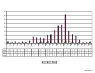
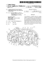
Figure 1 - Article <strong>06</strong>-8-5<br />
NOTE<br />
MONITOR THE PCM THROTTLE POSITION PID<br />
AFTER THE LAST BUTTON IS PRESSED.<br />
1. Self Test Diagnostic Procedure - Static Test<br />
NOTE<br />
THERE WILL BE A SLIGHT DELAY FROM WHEN<br />
a. Connect the diagnostic scan tool (DST) to a THE LAST BUTTON IS PRESSED AND THE<br />
power source that is not interrupted when CLUSTER LAMP FLASHES DIAGNOSTIC CODES.<br />
the ignition switch changes positions. With<br />
the ignition switch in the RUN position, set NOTE<br />
the DST to monitor the powertrain control IF THE SELF-TEST WILL NOT START OR<br />
module (PCM) throttle position PID while the CANNOT BE COMPLETED AFTER MULTIPLE<br />
speed control actuator carries out the<br />
ATTEMPTS, GO TO THE VEHICLE WSM<br />
self-test.<br />
SYMPTOM CHART.<br />
b. Enter self-test diagnostics by firmly pressing<br />
and holding the speed control OFF switch<br />
while quickly cycling the ignition switch from<br />
RUN-to-OFF-to-RUN, making sure the<br />
engine does not start and is not running.<br />
e. Follow the list below for diagnostic flash<br />
codes, then go to the WSM Symptom Chart.<br />
PAGE 2