710 and 711 Flashers Installation Guide - Code 3 Public Safety ...
710 and 711 Flashers Installation Guide - Code 3 Public Safety ...
710 and 711 Flashers Installation Guide - Code 3 Public Safety ...

You also want an ePaper? Increase the reach of your titles
YUMPU automatically turns print PDFs into web optimized ePapers that Google loves.
Operation as a Headlight Flasher (12v Operation only)<br />
Flash Mode 1 <strong>Installation</strong><br />
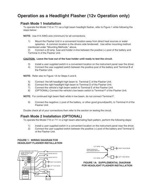
To operate the Model <strong>710</strong> or <strong>711</strong> as a high beam headlight flasher, refer to Figure 1 while following the<br />
steps below:<br />
NOTE: Use #14 AWG wire (minimum) for all connections.<br />
1) Mount the Flasher Unit in a convenient location away from direct heat sources or water<br />
splashes. A common location is the drivers side fenderwell. Use either mounting method<br />
mentioned under “Mounting Methods,” above.<br />
2) Connect a 20 amp. fuse <strong>and</strong> holder in-line between the positive (+) post of the battery <strong>and</strong><br />
Terminal A of the Flasher Unit.<br />
CAUTION: Leave the fuse out of the fuse holder until ready to test the circuit.<br />
3) Install a user supplied switch in a convenient location on the instrument panel near the driver.<br />
4) Connect the user supplied switch between the positive post of the battery <strong>and</strong> Terminal B of<br />
the Flasher Unit.<br />
NOTE: Refer also to Figure 1A for Steps 5 <strong>and</strong> 6.<br />
5) Connect the left headlight high beam to Terminal C of the Flasher Unit.<br />
6) Connect the right headlight high beam to Terminal D of the Flasher Unit.<br />
7) Connect the vehicle’s high beam switch to Terminal E of the Flasher Unit.<br />
8) (OPTIONAL) Connect the vehicle’s low beam switch to Terminal F of the Flasher Unit.<br />
NOTE: For continued high beam flash while in low beam, do not connect Terminal F.<br />
9) Connect the negative (-) post of the battery, or other good ground(earth), to Terminal H of the<br />
Flasher Unit.<br />
Double check all of your connections then refer to the section on testing the circuit.<br />
Flash Mode 2 <strong>Installation</strong> (OPTIONAL)<br />
To operate the Model <strong>710</strong> or <strong>711</strong> in a high beam alternating flash pattern, perform the following steps:<br />
1) Install a user supplied switch in a convenient location on the instrument panel near the driver.<br />
2) Connect the user supplied switch between the positive (+) post of the battery <strong>and</strong> Terminal G<br />
of the Flasher Unit.<br />
FIGURE 1: WIRING DIAGRAM FOR<br />
HEADLIGHT FLASHER INSTALLATION<br />
FOR CONTINUED HIGH BEAM<br />
FLASH WHILE IN LOW<br />
BEAM. DO NOT USE<br />
TERMINAL F<br />
NEGATIVE<br />
MODE #2<br />
LOW<br />
HIGH<br />
H<br />
G<br />
F<br />
E<br />
D<br />
C<br />
B<br />
A<br />
20 AMP<br />
FUSE<br />
VEHICLE'S LOW BEAM SWITCH<br />
VEHICLE'S HIGH BEAM SWITCH<br />
FLASHER ON - MODE #1<br />
14 AWG MIN.<br />
RIGHT HIGH BEAM<br />
LEFT HIGH BEAM<br />
CUT HERE<br />
FROM VEHICLE'S<br />
HIGH BEAM SWITCH<br />
CUT HERE<br />
RIGHT HIGH BEAM<br />
LEFT HIGH BEAM<br />
FIGURE 1A: SUPPLEMENTAL DIAGRAM<br />
FOR HEADLIGHT FLASHER INSTALLATION<br />
CODE 3<br />
— +<br />
BATTERY