Maxon OvenPak Flamerod and Igniter Setup - Megtec Systems
Maxon OvenPak Flamerod and Igniter Setup - Megtec Systems
Maxon OvenPak Flamerod and Igniter Setup - Megtec Systems

You also want an ePaper? Increase the reach of your titles
YUMPU automatically turns print PDFs into web optimized ePapers that Google loves.
Technical Bulletin<br />
<strong>Maxon</strong> <strong>OvenPak</strong><br />
<strong>Flamerod</strong> <strong>and</strong> <strong>Igniter</strong> <strong>Setup</strong><br />
Caution!<br />
Before changing the flame rod or igniter, make sure<br />
that all power is off to the dryer or oxidizer. As long as<br />
power is present at the dryer, the flame rod circuit will<br />
have a voltage potential of up to 480VAC. The ignition<br />
transformer may have a potential voltage of 7500VAC.<br />
Setting or replacing the igniter or flame rod on a <strong>Maxon</strong><br />
burner involves identifying the burner model, then the<br />
proper flame rod <strong>and</strong> igniter needed.<br />
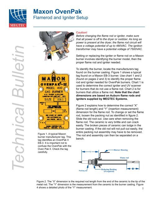
To identify the burner, locate the manufacturers tag<br />
found on the burner casting. Figure 1 shows a typical<br />
tag found on a <strong>Maxon</strong> EB-3 burner. Use chart 1 <strong>and</strong> 2<br />
(found on pages 2 <strong>and</strong> 3) to identify the proper flame<br />
rod <strong>and</strong> igniter needed for <strong>OvenPak</strong> burners. Chart 1 is<br />
used to determine the correct igniter <strong>and</strong> UV scanner<br />
for burners that do not use a flame rod. Chart 2 is for<br />
burners that utilize a flame rod. Note that the chart<br />
dimensions are based on Auburn flame rods <strong>and</strong><br />
igniters supplied by MEGTEC <strong>Systems</strong>.<br />
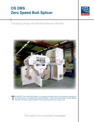
Figure 1. A typical <strong>Maxon</strong><br />
burner manufacturer tag. This<br />
tag identifies an <strong>OvenPak</strong> II<br />
EB-3. It is important not to<br />
confuse the <strong>OvenPak</strong> with the<br />
Oven Pak II. Check the tag<br />
carefully.<br />
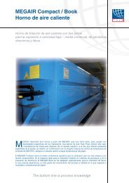
Figure 2 explains how to determine the correct “X”<br />
(flame rod length) <strong>and</strong> “Y” (insertion measurement)<br />
dimension for the flame rod. To change or set the flame<br />
rod, loosen the packing nut as identified in figure 2.<br />
Slide the old root out. Use care when removing the<br />
flame rod. The ceramic is very brittle <strong>and</strong> can crack<br />
easily. The broken pieces of ceramic can lodge in the<br />
burner casting. If the old rod will not pull out easily, the<br />
entire packing nut assembly may have to be removed.<br />
The rod <strong>and</strong> assembly can then be separated on a<br />
bench.<br />
Figure 2. The “X” dimension is the required rod length from the end of the ceramic to the tip of the<br />
metal rod. The “Y” dimension is the measurement from the ceramic to the burner casting. Figure<br />
4 shows a detailed photo of the “Y” measurement.<br />
1
Technical Bulletin<br />
<strong>Maxon</strong> <strong>OvenPak</strong><br />
<strong>Flamerod</strong> <strong>and</strong> <strong>Igniter</strong> <strong>Setup</strong><br />
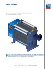
Figure 3. To set the flamerod,<br />
measure from the edge of the<br />
casting to the end of the ceramic.<br />
Before inserting the new rod, check the rajah connector<br />
(figure 3) on the end of the rod, tighten it if is loose. Slide<br />
the new rod in <strong>and</strong> tighten the packing nut finger tight.<br />
Using a ruler, measure the distance from the edge of<br />
the flame rod ceramic to the casting of the burner as<br />
shown in figure 3. When the flame rod is at the correct “Y”<br />
dimension, tighten the packing nut with a wrench. Do not<br />
over tighten the packing nut. The packing nut assembly<br />
has a rubber O-ring inside. Over tightening may push<br />
the ring out of the position <strong>and</strong> allow gas to escape from<br />
the burner during operation. After tightening the rod<br />
in place, check the insertion measurement again <strong>and</strong><br />
adjust it if necessary.<br />
To replace the igniter, follow the same procedure as<br />
detailed for the flame rod. Use the “Z” dimension as<br />
shown in chart 1 or 2 for the proper insertion depth. Figure 4 explains the required “Z”<br />
(insertion measurement) for the igniter.<br />
Note that the insertion <strong>and</strong> flame rod dimensions are critical measurements for<br />
proper burner light off <strong>and</strong> flame sensing. If the flame rod is inserted to far, the ceramic<br />
will be exposed to the burner flame causing it to crack. Any cracks that form will fill with<br />
carbon deposits. Carbon is a conductor <strong>and</strong> will allow the flame signal to ‘ground out’<br />
resulting in a flameout. If the flame rod is too far back, the rod may be out of the path of the<br />
burner flame at high fire causing a flameout.<br />
Figure 4. The “Z” dimension determines the insertion depth of the igniter. Measure from the end of<br />
the ceramic to the burner casting.<br />
2
Technical Bulletin<br />
<strong>Maxon</strong> <strong>OvenPak</strong><br />
<strong>Flamerod</strong> <strong>and</strong> <strong>Igniter</strong> <strong>Setup</strong><br />
The igniter position is also important. The tip of the<br />
igniter produces a high voltage spark that ignited<br />
the pilot gas when the burner starts. If the igniter is<br />
inserted to far, the tip may ground against the internal<br />
parts of the burner. This will prevent an ignition spark<br />
from being generated, resulting in the pilot gas not<br />
lighting <strong>and</strong> the burner shutting down. With the igniter<br />
pulled to far back from the required “Z” dimension,<br />
the spark gap may be to large to produce a strong<br />
enough spark to lithe the pilot gas or no spark may be<br />
produced at all, resulting in the burner locking out <strong>and</strong><br />
shutting down.<br />
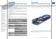
Figure 5. Relocate the flamerod<br />
ground wire from the site port screw<br />
to the burner casting bolts<br />
<strong>Flamerod</strong>s <strong>and</strong> igniters should be replaced annually.<br />
To improve flame rod signal strength, it may be helpful<br />
to move the signal ground wire from the connection<br />
at the burner site port to the casting of the burner as<br />
shown in figure 5.<br />
Please note: Local codes may require that a factory trained technician service your<br />
burner.<br />
UV Scanner P/N<br />
121231 For<br />
Burner<br />
EBC-2SP<br />
EBC-3SP<br />
EBC-4SP<br />
EBC-5SP<br />
EBC-6SP<br />
508<br />
515<br />
525<br />
535<br />
550<br />
<strong>Igniter</strong> P/N<br />
134031 “Z”<br />
Dimension<br />
4 3/4” (121)<br />
5 1/8” (130)<br />
4 3/4” (121)<br />
4 3/4” (121)<br />
4 3/4” (121)<br />
4 3/4” (121)<br />
5 1/8” (130)<br />
4 3/4” (121)<br />
4 3/4” (121)<br />
4 3/4” (121)<br />
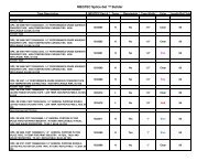
Chart 1. This chart is used for burners that<br />
use a UV-scanner instead of a flamerod.<br />
The “Z” dimension is still used to set the<br />
3
Technical Bulletin<br />
<strong>Maxon</strong> <strong>OvenPak</strong><br />
<strong>Flamerod</strong> <strong>and</strong> <strong>Igniter</strong> <strong>Setup</strong><br />
Flame Rods<br />
<strong>Igniter</strong>s<br />
Burner<br />
“X” Dimension “Y” Dimension Flame Rod P/N 134031 “Z”<br />
(mm)<br />
(mm) Part Number Dimension (mm)<br />
<strong>OvenPak</strong><br />
EB1<br />
EB2<br />
6” (152)<br />
6” (152)<br />
4-13/16” (122)<br />
4-13/16” (122)<br />
134004<br />
134004<br />
4-13/16” (122)<br />
4-13/16” (122)<br />
EB2-MRV<br />
EB3<br />
6” (152)<br />
8” (203)<br />
4-13/16” (122)<br />
4-13/16” (122)<br />
134004<br />
134005<br />
4-13/16” (122)<br />
5” (127)<br />
EB3-MRV<br />
EB4<br />
8” (203)<br />
8” (203)<br />
4-13/16” (122)<br />
3-3/8” (86)<br />
134005<br />
134005<br />
5” (127)<br />
4-3/4” (121)<br />
EB4-MRV<br />
EB5<br />
8” (203)<br />
12-3/4" (323)<br />
3-3/8” (86)<br />
3-3/8” (86)<br />
134005<br />
134007<br />
4-3/4” (121)<br />
4-3/4” (121)<br />
EB5-MRV<br />
EB6<br />
12-3/4" (323)<br />
12-3/4" (323)<br />
3-3/8” (86)<br />
2-11/16” (69)<br />
134007<br />
134007<br />
4-3/4” (121)<br />
4-13/16” (122)<br />
EB7<br />
405<br />
12-3/4" (323)<br />
6” (152)<br />
2-11/16” (69)<br />
4-13/16” (122)<br />
134007<br />
134004<br />
4-13/16” (122)<br />
4-13/16” (122)<br />
407M<br />
408<br />
6” (152)<br />
6” (152)<br />
4-13/16” (122)<br />
4-13/16” (122)<br />
134004<br />
134004<br />
4-13/16” (122)<br />
4-13/16” (122)<br />
408M<br />
412M<br />
6” (152)<br />
6” (152)<br />
4-13/16” (122)<br />
4-13/16” (122)<br />
134004<br />
134004<br />
4-13/16” (122)<br />
4-13/16” (122)<br />
413M<br />
415<br />
6” (152)<br />
6” (152)<br />
4-13/16” (122)<br />
4-13/16” (122)<br />
134004<br />
134004<br />
4-13/16” (122)<br />
5” (127)<br />
422M<br />
425<br />
6” (152)<br />
8” (203)<br />
4-13/16” (122)<br />
3-3/8” (86)<br />
134004<br />
134005<br />
5” (127)<br />
4-3/4” (121)<br />
432M<br />
435<br />
8” (203)<br />
8” (203)<br />
3-3/8” (86)<br />
3-3/8” (86)<br />
134005<br />
134005<br />
4-3/4” (121)<br />
4-3/4” (121)<br />
442M<br />
445<br />
8” (203)<br />
12-3/4” (323)<br />
3-3/8” (86)<br />
2-11/16” (69)<br />
134005<br />
134007<br />
4-3/4” (121)<br />
4-13/16” (122)<br />
456M<br />
470M<br />
12-3/4” (323)<br />
12-3/4” (323)<br />
2-11/16” (69)<br />
2-11/16” (69)<br />
134007<br />
134007<br />
4-13/16” (122)<br />
4-13/16” (122)<br />
487M 12-3/4” (323) 2-11/16” (69) 134007 4-13/16” (122)<br />
<strong>OvenPak</strong> II<br />
EB1<br />
EB2<br />
8” (203)<br />
8” (203)<br />
3-1/2” (89)<br />
3-1/2” (89)<br />
134005<br />
134005<br />
5-9/16” (141)<br />
5-9/16” (141)<br />
EB3<br />
EB4<br />
8” (203)<br />
12-3/4” (323)<br />
3-1/2” (89)<br />
2-1/2” (64)<br />
134005<br />
134007<br />
4-3/4” (121)<br />
4-3/8” (111)<br />
EB5<br />
EB6<br />
12-3/4” (323)<br />
*1<br />
2-1/2” (64)<br />
*1<br />
134007<br />
*1<br />
4-3/8” (111)<br />
3-1/4” (83)<br />
EB7 *1 *1 *1 3-1/4” (83)<br />
*1 – <strong>Flamerod</strong> option not available for these burners<br />
Chart 2. This chart lists all of the X, Y, <strong>and</strong> Z dimensions for <strong>OvenPak</strong> burners that use a<br />
flamerod.<br />
For further information, availability, please contact your nearest MEGTEC office by visiting<br />
www.megtec.com <strong>and</strong> click on parts <strong>and</strong> upgrades or email to info@megtec.com.<br />
TCB-019-10/30/2009_<strong>Maxon</strong> Ovenpak <strong>Flamerod</strong> <strong>and</strong> <strong>Igniter</strong> <strong>Setup</strong><br />
4