Adobe Photoshop PDF - Moellerpunch.com
Adobe Photoshop PDF - Moellerpunch.com
Adobe Photoshop PDF - Moellerpunch.com

Create successful ePaper yourself
Turn your PDF publications into a flip-book with our unique Google optimized e-Paper software.
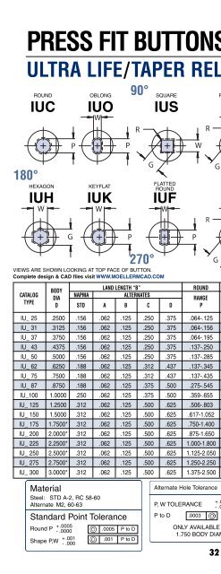
TECHNICAL TOPICS<br />
Clearance<br />
Clearance between punch and die is based upon type of material being stamped, material thickness, finish requirement of hole<br />
and anticipated tool life. It is expressed as a total percentage of material thickness being stamped. It is important to remember<br />
that the punch determines hole size and the die determines slug size. As a rule, optimal clearance provides flat, sharp and clean<br />
punching with minimum tool load. Insufficient clearance results in minimum burr and rollover, but tool life is shortened due to high<br />
tool loads. Excessive clearance results in deformation and larger rollover but increased tool life. Below are some general<br />
guidelines for different types of material being stamped. The values shown are re<strong>com</strong>mended total die clearance for general<br />
purpose holes using non-ejector punches. By doubling the amount of clearance and using ejector punches, anticipated tool life<br />
will be greatly increased. Most of the punch wear is produced by stripping forces when the punch is being withdrawn. The<br />
increased clearance by using ejector punches helps keep tool wear to a minimum.<br />
B<br />
LOSS<br />
OF RAD<br />
SBR<br />
D<br />
ROLL OVER<br />
BURNISH AREA<br />
BREAK OUT<br />
BURR<br />
STRAIGHT BEFORE RADIUS CHART<br />
P<br />
.500<br />
.469<br />
.438<br />
.406<br />
.375<br />
.344<br />
.313<br />
.281<br />
.250<br />
.219<br />
.188<br />
.156<br />
.125<br />
.093<br />
.062<br />
.031<br />
.000<br />
.100 .200 .300 .400 .500<br />
.050 .150 .250 .350 .450<br />
R 1/2<br />
64<br />
MANUFACTURING<br />
COMPANY<br />
Material Soft Hard<br />
Aluminum 10% 12%<br />
Brass/Copper 6% 8%<br />
Steel (Low Carbon) 10% 12%<br />
Steel (High Carbon) 18% 20%<br />
To approximate SBR calculate (D-P) ÷ 2<br />
use that value shown in blue at top of chart.<br />
Follow line down until it intersects with<br />
blend RAD. Move over to the left to find loss<br />
of RAD value. B-Loss of RAD= SBR.<br />
Example:<br />
D=.625 P=.321 B=.75<br />
(.625-.321) ÷ 2 = .152<br />
Loss of RAD = .36<br />
(B) .75 - (LOR) .36 = (SBR) .39