
You also want an ePaper? Increase the reach of your titles
YUMPU automatically turns print PDFs into web optimized ePapers that Google loves.
<strong>CdA</strong> - TeCHniCAL SPeCiFiCATiOnS<br />
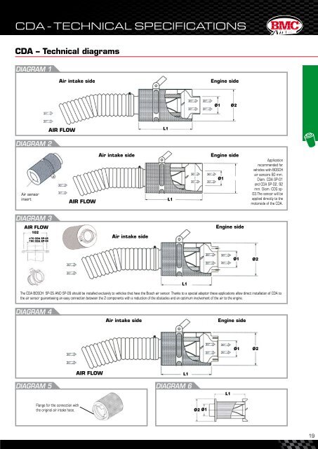
CDA – Technical diagrams<br />
DIAGRAM 1<br />
DIAGRAM 2<br />
Air sensor<br />
insert<br />
DIAGRAM 3<br />
AIR FLOW<br />
102<br />
70 CDA SP-05<br />
80 CDA SP-09<br />
AIR FLOW<br />
Air intake side Engine side<br />
DIAGRAM 5 DIAGRAM 6<br />
Flange for the connection with<br />
the original air intake hose.<br />
AIR FLOW<br />
Air intake side<br />
L1<br />
L1<br />
L1<br />
Ø2 Ø1<br />
Ø1<br />
L1<br />
Ø2<br />
Engine side<br />
Ø1 Ø2<br />
Air intake side Engine side<br />
Ø1 Ø2<br />
Application<br />
recommended for<br />
vehicles with BOSCH<br />
air sensors 80 mm.<br />
Diam. CDA SP-01<br />
and CDA SP-02, 92<br />
mm. Diam. CDS sp-<br />
03.The sensor will be<br />
applied directly to the<br />
motorside of the CDA.<br />
The CDA BOSCH SP-05 AND SP-09 should be installed exclusivly to vehicles that have the Bosch air sensor. Thanks to a special adaptor these applications allow direct installation of CDA to<br />
the air sensor guaranteeing an easy connection between the 2 components with a reduction of the obstacles and an optimum involvement of the air to the engine.<br />
DIAGRAM 4<br />
Air intake side Engine side<br />
AIR FLOW<br />
L1<br />
Ø1<br />
Ø2<br />
®<br />
19