Boom Lift Capacity Charts - Link-Belt Construction Equipment
Boom Lift Capacity Charts - Link-Belt Construction Equipment
Boom Lift Capacity Charts - Link-Belt Construction Equipment

You also want an ePaper? Increase the reach of your titles
YUMPU automatically turns print PDFs into web optimized ePapers that Google loves.
10<br />
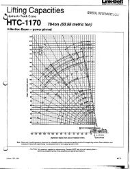
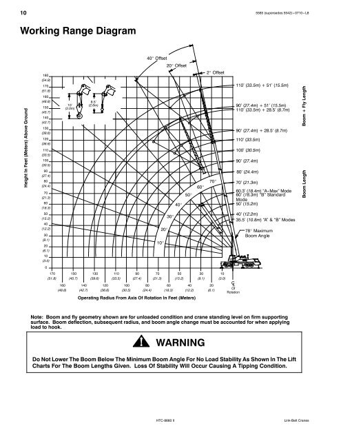
Working Range Diagram<br />
Height In Feet (Meters) Above Ground<br />
180<br />
(54.9)<br />
170<br />
(51.8)<br />
160<br />
(48.8)<br />
150<br />
(45.7)<br />
140<br />
(42.7)<br />
130<br />
(39.6)<br />
120<br />
(36.6)<br />
110<br />
(33.5)<br />
100<br />
(30.5)<br />
90<br />
(27.4)<br />
80<br />
(24.4)<br />
70<br />
(21.3)<br />
60<br />
(18.3)<br />
50<br />
(15.2)<br />
40<br />
(12.2)<br />
30<br />
(9.1)<br />
20<br />
(6.1)<br />
10<br />
(3.0)<br />
0<br />
170<br />
(51.8)<br />
160<br />
(48.8)<br />
10’<br />
(3.0m)<br />
150<br />
(45.7)<br />
140<br />
(42.7)<br />
8.5’<br />
(2.6m)<br />
130<br />
(39.6)<br />
120<br />
(36.6)<br />
110<br />
(33.5)<br />
100<br />
(30.5)<br />
90<br />
(27.4)<br />
40� Offset<br />
80<br />
(24.4)<br />
10�<br />
70<br />
(21.3)<br />
5565 (supersedes 5542)--- 0710--- L8<br />
Note: <strong>Boom</strong> and fly geometry shown are for unloaded condition and crane standing level on firm supporting<br />
surface. <strong>Boom</strong> deflection, subsequent radius, and boom angle change must be accounted for when applying<br />
load to hook.<br />
20�<br />
20� Offset<br />
30�<br />
60<br />
(18.3)<br />
40�<br />
50<br />
(15.2)<br />
50�<br />
40<br />
(12.2)<br />
Operating Radius From Axis Of Rotation In Feet (Meters)<br />
60�<br />
30<br />
(9.1)<br />
WARNING<br />
2� Offset<br />
70�<br />
20<br />
(6.1)<br />
10<br />
(3.0)<br />
C L<br />
Of<br />
Rotation<br />
110’ (33.5m) + 51’ (15.5m)<br />
90’ (27.4m) + 51’ (15.5m)<br />
110’ (33.5m) + 28.5’ (8.7m)<br />
90’ (27.4m) + 28.5’ (8.7m)<br />
110’ (33.5m)<br />
100’ (30.5m)<br />
90’ (27.4m)<br />
80’ (24.4m)<br />
70’ (21.3m)<br />
60.3’ (18.4m) “A -Max” Mode<br />
60’ (18.3m) “B” Standard<br />
Mode<br />
50’ (15.2m)<br />
40’ (12.2m)<br />
35.5’ (10.8m) “A” & “B” Modes<br />
78� Maximum<br />
<strong>Boom</strong> Angle<br />
Do Not Lower The <strong>Boom</strong> Below The Minimum <strong>Boom</strong> Angle For No Load Stability As Shown In The <strong>Lift</strong><br />
<strong>Charts</strong> For The <strong>Boom</strong> Lengths Given. Loss Of Stability Will Occur Causing A Tipping Condition.<br />
HTC-8660 II <strong>Link</strong>-<strong>Belt</strong> Cranes<br />
<strong>Boom</strong> Length <strong>Boom</strong> + Fly Length