LM2940/LM2940C 1A Low Dropout Regulator - Avtanski.com ...
LM2940/LM2940C 1A Low Dropout Regulator - Avtanski.com ...
LM2940/LM2940C 1A Low Dropout Regulator - Avtanski.com ...

You also want an ePaper? Increase the reach of your titles
YUMPU automatically turns print PDFs into web optimized ePapers that Google loves.
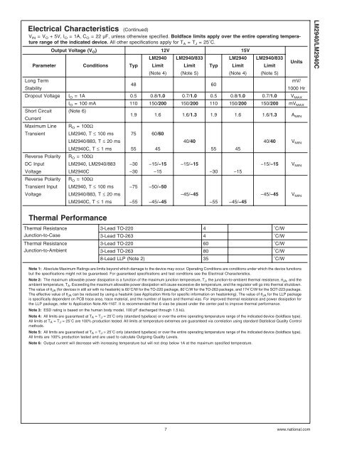
Electrical Characteristics (Continued)<br />
V IN =V O + 5V, I O = <strong>1A</strong>, C O = 22 µF, unless otherwise specified. Boldface limits apply over the entire operating temperature<br />
range of the indicated device. All other specifications apply for T A =T J = 25˚C.<br />
Output Voltage (V O ) 12V 15V<br />
<strong>LM2940</strong> <strong>LM2940</strong>/833 <strong>LM2940</strong> <strong>LM2940</strong>/833<br />
Parameter Conditions Typ Limit Limit Typ Limit Limit<br />
(Note 4) (Note 5) (Note 4) (Note 5)<br />
Long Term<br />
Stability<br />
48 60<br />
Units<br />
mV/<br />
1000 Hr<br />
<strong>LM2940</strong>/<strong>LM2940</strong>C<br />
<strong>Dropout</strong> Voltage I O = <strong>1A</strong> 0.5 0.8/1.0 0.7/1.0 0.5 0.8/1.0 0.7/1.0 V MAX<br />
I O = 100 mA 110 150/200 150/200 110 150/200 150/200 mV MAX<br />
Short Circuit (Note 6)<br />
Current<br />
1.9 1.6 1.6/1.3 1.9 1.6 1.6/1.3 A MIN<br />
Maximum Line R O = 100Ω<br />
Transient <strong>LM2940</strong>, T ≤ 100 ms 75 60/60<br />
Reverse Polarity<br />
<strong>LM2940</strong>/883, T ≤ 20 ms 40/40 40/40 V MIN<br />
<strong>LM2940</strong>C, T ≤ 1 ms 55 45 55 45<br />
R O = 100Ω<br />
DC Input <strong>LM2940</strong>, <strong>LM2940</strong>/883 −30 −15/−15 −15/−15 −15/−15 V MIN<br />
Voltage <strong>LM2940</strong>C −30 −15 −30 −15<br />
Reverse Polarity R O = 100Ω<br />
Transient Input <strong>LM2940</strong>, T ≤ 100 ms −75 −50/−50<br />
Voltage <strong>LM2940</strong>/883, T ≤ 20 ms −45/−45 −45/−45 V MIN<br />
<strong>LM2940</strong>C, T ≤ 1 ms −55 −45/−45 −55 −45/−45<br />
Thermal Performance<br />
Thermal Resistance<br />
Junction-to-Case<br />
Thermal Resistance<br />
Junction-to-Ambient<br />
3-Lead TO-220 4 ˚C/W<br />
3-Lead TO-263 4 ˚C/W<br />
3-Lead TO-220 60 ˚C/W<br />
3-Lead TO-263 80 ˚C/W<br />
8-Lead LLP (Note 2) 35 ˚C/W<br />
Note 1: Absolute Maximum Ratings are limits beyond which damage to the device may occur. Operating Conditions are conditions under which the device functions<br />
but the specifications might not be guaranteed. For guaranteed specifications and test conditions see the Electrical Characteristics.<br />
Note 2: The maximum allowable power dissipation is a function of the maximum junction temperature, T J , the junction-to-ambient thermal resistance, θ JA , and the<br />
ambient temperature, T A . Exceeding the maximum allowable power dissipation will cause excessive die temperature, and the regulator will go into thermal shutdown.<br />
The value of θ JA (for devices in still air with no heatsink) is 60˚C/W for the TO-220 package, 80˚C/W for the TO-263 package, and 174˚C/W for the SOT-223 package.<br />
The effective value of θ JA can be reduced by using a heatsink (see Application Hints for specific information on heatsinking). The value of θ JA for the LLP package<br />
is specifically dependent on PCB trace area, trace material, and the number of layers and thermal vias. For improved thermal resistance and power dissipation for<br />
the LLP package, refer to Application Note AN-1187. It is re<strong>com</strong>mended that 6 vias be placed under the center pad to improve thermal performance.<br />
Note 3: ESD rating is based on the human body model, 100 pF discharged through 1.5 kΩ.<br />
Note 4: All limits are guaranteed at T A =T J = 25˚C only (standard typeface) or over the entire operating temperature range of the indicated device (boldface type).<br />
All limits at T A =T J = 25˚C are 100% production tested. All limits at temperature extremes are guaranteed via correlation using standard Statistical Quality Control<br />
methods.<br />
Note 5: All limits are guaranteed at T A =T J = 25˚C only (standard typeface) or over the entire operating temperature range of the indicated device (boldface type).<br />
All limits are 100% production tested and are used to calculate Outgoing Quality Levels.<br />
Note 6: Output current will decrease with increasing temperature but will not drop below <strong>1A</strong> at the maximum specified temperature.<br />
7<br />
www.national.<strong>com</strong>