Dixon Oil Field Products Catalog - Hydraulic Hose
Dixon Oil Field Products Catalog - Hydraulic Hose
Dixon Oil Field Products Catalog - Hydraulic Hose
Create successful ePaper yourself
Turn your PDF publications into a flip-book with our unique Google optimized e-Paper software.
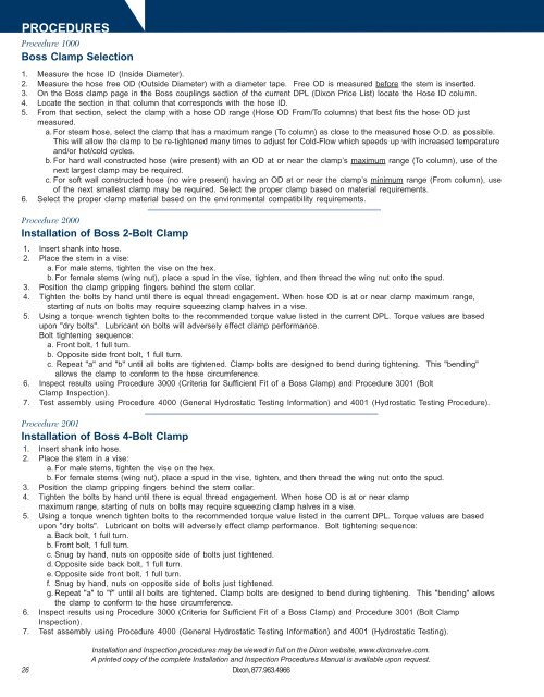
PROCEDURES<br />
Procedure 1000<br />
Boss Clamp Selection<br />
1. Measure the hose ID (Inside Diameter).<br />
2. Measure the hose free OD (Outside Diameter) with a diameter tape. Free OD is measured before the stem is inserted.<br />
3. On the Boss clamp page in the Boss couplings section of the current DPL (<strong>Dixon</strong> Price List) locate the <strong>Hose</strong> ID column.<br />
4. Locate the section in that column that corresponds with the hose ID.<br />
5. From that section, select the clamp with a hose OD range (<strong>Hose</strong> OD From/To columns) that best fits the hose OD just<br />
measured.<br />
a. For steam hose, select the clamp that has a maximum range (To column) as close to the measured hose O.D. as possible.<br />
This will allow the clamp to be re-tightened many times to adjust for Cold-Flow which speeds up with increased temperature<br />
and/or hot/cold cycles.<br />
b. For hard wall constructed hose (wire present) with an OD at or near the clamp’s maximum range (To column), use of the<br />
next largest clamp may be required.<br />
c. For soft wall constructed hose (no wire present) having an OD at or near the clamp’s minimum range (From column), use<br />
of the next smallest clamp may be required. Select the proper clamp based on material requirements.<br />
6. Select the proper clamp material based on the environmental compatibility requirements.<br />
Procedure 2000<br />
Installation of Boss 2-Bolt Clamp<br />
1. Insert shank into hose.<br />
2. Place the stem in a vise:<br />
a. For male stems, tighten the vise on the hex.<br />
b. For female stems (wing nut), place a spud in the vise, tighten, and then thread the wing nut onto the spud.<br />
3. Position the clamp gripping fingers behind the stem collar.<br />
4. Tighten the bolts by hand until there is equal thread engagement. When hose OD is at or near clamp maximum range,<br />
starting of nuts on bolts may require squeezing clamp halves in a vise.<br />
5. Using a torque wrench tighten bolts to the recommended torque value listed in the current DPL. Torque values are based<br />
upon "dry bolts". Lubricant on bolts will adversely effect clamp performance.<br />
Bolt tightening sequence:<br />
a. Front bolt, 1 full turn.<br />
b. Opposite side front bolt, 1 full turn.<br />
c. Repeat "a" and "b" until all bolts are tightened. Clamp bolts are designed to bend during tightening. This "bending"<br />
allows the clamp to conform to the hose circumference.<br />
6. Inspect results using Procedure 3000 (Criteria for Sufficient Fit of a Boss Clamp) and Procedure 3001 (Bolt<br />
Clamp Inspection).<br />
7. Test assembly using Procedure 4000 (General Hydrostatic Testing Information) and 4001 (Hydrostatic Testing Procedure).<br />
Procedure 2001<br />
Installation of Boss 4-Bolt Clamp<br />
1. Insert shank into hose.<br />
2. Place the stem in a vise:<br />
a. For male stems, tighten the vise on the hex.<br />
b. For female stems (wing nut), place a spud in the vise, tighten, and then thread the wing nut onto the spud.<br />
3. Position the clamp gripping fingers behind the stem collar.<br />
4. Tighten the bolts by hand until there is equal thread engagement. When hose OD is at or near clamp<br />
maximum range, starting of nuts on bolts may require squeezing clamp halves in a vise.<br />
5. Using a torque wrench tighten bolts to the recommended torque value listed in the current DPL. Torque values are based<br />
upon "dry bolts". Lubricant on bolts will adversely effect clamp performance. Bolt tightening sequence:<br />
a. Back bolt, 1 full turn.<br />
b. Front bolt, 1 full turn.<br />
c. Snug by hand, nuts on opposite side of bolts just tightened.<br />
d. Opposite side back bolt, 1 full turn.<br />
e. Opposite side front bolt, 1 full turn.<br />
f. Snug by hand, nuts on opposite side of bolts just tightened.<br />
g. Repeat "a" to "f" until all bolts are tightened. Clamp bolts are designed to bend during tightening. This "bending" allows<br />
the clamp to conform to the hose circumference.<br />
6. Inspect results using Procedure 3000 (Criteria for Sufficient Fit of a Boss Clamp) and Procedure 3001 (Bolt Clamp<br />
Inspection).<br />
7. Test assembly using Procedure 4000 (General Hydrostatic Testing Information) and 4001 (Hydrostatic Testing).<br />
26<br />
Installation and Inspection procedures may be viewed in full on the <strong>Dixon</strong> website, www.dixonvalve.com.<br />
A printed copy of the complete Installation and Inspection Procedures Manual is available upon request.<br />
<strong>Dixon</strong>, 877.963.4966


