History of Wireless Local Area Networks (WLANs) - Information ...
History of Wireless Local Area Networks (WLANs) - Information ...
History of Wireless Local Area Networks (WLANs) - Information ...

You also want an ePaper? Increase the reach of your titles
YUMPU automatically turns print PDFs into web optimized ePapers that Google loves.
George Mason University Law School Conference, <strong>Information</strong> Economy Project, Arlington, VA., April 4, 2008<br />
supported 3 non-overlapping channels in the 2.4 GHz band<br />
and such channels could be coincident with those <strong>of</strong> the<br />
original direct sequence PHY such that real time mixed mode<br />
operation was straightforward. Also with 3 channels instead<br />
<strong>of</strong> 2 in Micrilor’s proposal, the Harris system had more<br />
frequency agility to avoid interference such as a microwave<br />
oven in the ISM band. And the Harris system went 11 Mb/s<br />
instead <strong>of</strong> 10 Mb/s for Micrilor.<br />
However in 1998, there was an accepted orthodoxy in the<br />
WLAN industry that the 10 dB processing gain requirement <strong>of</strong><br />
the FCC 15.247 rules meant the spreading sequences had to be<br />
10 chips in length or greater. The most common sequence in<br />
use from the original 900 MHz Proxim RangeLAN on through<br />
the 802.11 direct sequence PHY was the 11-chip Barker code.<br />
How, asked the WLAN community <strong>of</strong> Harris Semiconductor,<br />
was this 8-chip proposal ever going to be certifiable under<br />
15.247 rules?<br />
B. Harris Semiconductor convinces the FCC to accept 8chip<br />
MBOK<br />
In 1997, Harris Semiconductor’s approached the FCC with a<br />
description <strong>of</strong> their MBOK proposal. Harris submitted<br />
detailed mathematical analysis on how MBOK meets the<br />
10dB processing gain requirement along with measured<br />
results <strong>of</strong> the CW Jamming Margin tests from an independent<br />
test laboratory. Harris was able to prove that MBOK meets<br />
the 10dB processing gain requirement by summing processing<br />
gain from channel spreading and coding gain from the 8-chip<br />
Walsh codes. The FCC still debated the argument and industry<br />
support for such technology. The FCC decided not to allow<br />
MBOK until a commercial product was available for<br />
certification using the Harris MBOK chipset. Later in 1997 an<br />
independent set <strong>of</strong> FCC Part 15.247 tests were conduct on a<br />
PCMCIA 802.11 adaptor from Aironet (later acquired by<br />
Cisco System) and submitted for FCC approval. Aironet<br />
received FCC Part 15.247 approval on a PCMCIA adaptor<br />
based on Harris’ MBOK technology. Following Aironet’s<br />
FCC approval, MBOK was allowed under FCC Part 15.247<br />
rules.<br />
C. Completion <strong>of</strong> the IEEE 802.11b Process<br />
Despite Harris’ success in getting the FCC to agree that 8chip<br />
MBOK was certifiable, Harris was never able to get<br />
>50% <strong>of</strong> the 802.11 voting members to approve its MBOK<br />
proposal. But neither did Micrilor, though at one point<br />
Micrilor did get to precisely 50%. However, in July 1998 a<br />
“compromise” proposal was put forward which easily<br />
received >75% approval by <strong>of</strong>fering the excellent multipath<br />
performance <strong>of</strong> Micrilor with the backwards-compatible 3channel<br />
advantages <strong>of</strong> Harris at 11 Mb/s. This proposal was<br />
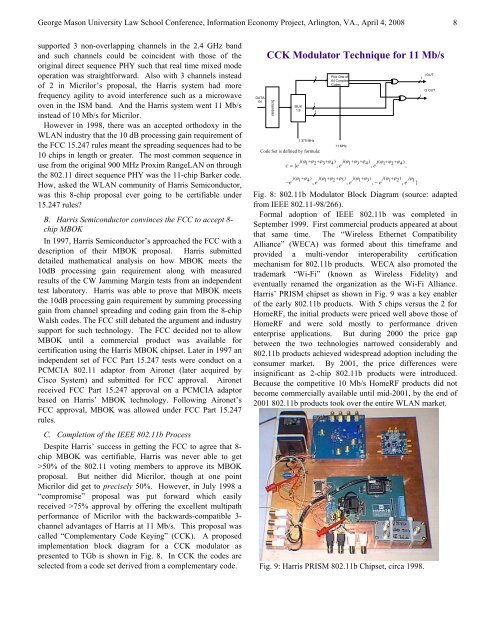
called “Complementary Code Keying” (CCK). A proposed<br />
implementation block diagram for a CCK modulator as<br />
presented to TGb is shown in Fig. 8. In CCK the codes are<br />
selected from a code set derived from a complementary code.<br />
DATA<br />
IN<br />
CCK Modulator Technique for 11 Mb/s<br />
Scrambler<br />
MUX<br />
1:8<br />
1.375 MHz<br />
Code Set is defined by formula:<br />
1<br />
6<br />
1<br />
Pick One <strong>of</strong><br />
64 Complex<br />
Codes<br />
11 MHz<br />
j( ϕ1+ ϕ2+ ϕ3+ ϕ4) j( ϕ1+ ϕ3+ ϕ4) j(<br />
ϕ1+ ϕ2+ ϕ4)<br />
c = { e , e , e<br />
,<br />
j( ϕ1+ ϕ4) j( ϕ1+ ϕ2+ ϕ3) j( ϕ1+ ϕ3) j( ϕ1+ ϕ2) jϕ1<br />
−e , e , e , −e<br />
, e }<br />
I OUT<br />
1<br />
1<br />
Q OUT<br />
Fig. 8: 802.11b Modulator Block Diagram (source: adapted<br />
from IEEE 802.11-98/266).<br />
Formal adoption <strong>of</strong> IEEE 802.11b was completed in<br />
September 1999. First commercial products appeared at about<br />
that same time. The “<strong>Wireless</strong> Ethernet Compatibility<br />
Alliance” (WECA) was formed about this timeframe and<br />
provided a multi-vendor interoperability certification<br />
mechanism for 802.11b products. WECA also promoted the<br />
trademark “Wi-Fi” (known as <strong>Wireless</strong> Fidelity) and<br />
eventually renamed the organization as the Wi-Fi Alliance.<br />
Harris’ PRISM chipset as shown in Fig. 9 was a key enabler<br />
<strong>of</strong> the early 802.11b products. With 5 chips versus the 2 for<br />
HomeRF, the initial products were priced well above those <strong>of</strong><br />
HomeRF and were sold mostly to performance driven<br />
enterprise applications. But during 2000 the price gap<br />
between the two technologies narrowed considerably and<br />
802.11b products achieved widespread adoption including the<br />
consumer market. By 2001, the price differences were<br />
insignificant as 2-chip 802.11b products were introduced.<br />
Because the competitive 10 Mb/s HomeRF products did not<br />
become commercially available until mid-2001, by the end <strong>of</strong><br />
2001 802.11b products took over the entire WLAN market.<br />
Fig. 9: Harris PRISM 802.11b Chipset, circa 1998.<br />
8