
You also want an ePaper? Increase the reach of your titles
YUMPU automatically turns print PDFs into web optimized ePapers that Google loves.
BYPASS SHOCK TECHNICAL MANUAL <br />
<br />
the <strong>shock</strong> fluid side will be pressurized. In this <br />
condition, the bearing housing and reservoir <br />
ends will be impossible to remove. <br />
Disassembling the <strong>shock</strong> in this state would <br />
be extremely dangerous, so the pressure <br />
must be released by carefully cracking open a <br />
fitting on the <strong>shock</strong>. On a remote reservoir <br />
<strong>shock</strong> loosen one of the hose fittings, and on <br />
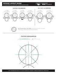
a piggy back <strong>shock</strong> loosen one of the <strong>bypass</strong> <br />
units. To crack open the <strong>bypass</strong> unit, first <br />
make sure the unit is adjusted fully open, <br />
then carefully unscrew the unit (the red or <br />
blue aluminum part). Be extremely cautious <br />
when doing this because the point when the <br />
pressure can escape and the cap shooting off <br />
is very close. In both cases, only open the <br />
fitting enough to let the pressure bleed out. <br />
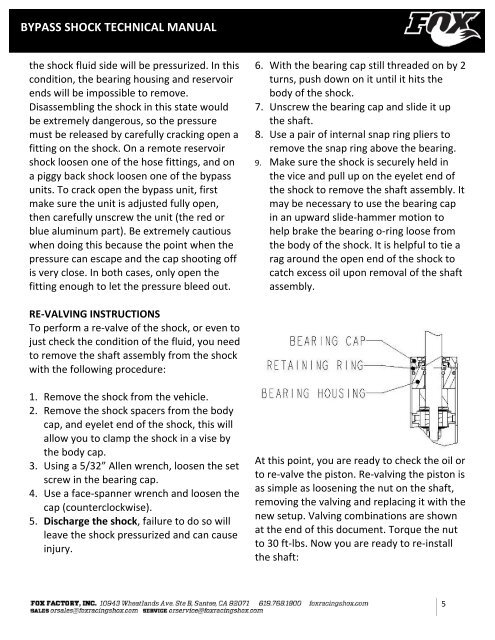
6. With the bearing cap still threaded on by 2 <br />
turns, push down on it until it hits the <br />
body of the <strong>shock</strong>. <br />
7. Unscrew the bearing cap and slide it up <br />
the shaft. <br />
8. Use a pair of internal snap ring pliers to <br />
remove the snap ring above the bearing. <br />
9. Make sure the <strong>shock</strong> is securely held in <br />
the vice and pull up on the eyelet end of <br />
the <strong>shock</strong> to remove the shaft assembly. It <br />
may be necessary to use the bearing cap <br />
in an upward slide-‐hammer motion to <br />
help brake the bearing o-‐ring loose from <br />
the body of the <strong>shock</strong>. It is helpful to tie a <br />
rag around the open end of the <strong>shock</strong> to <br />
catch excess oil upon removal of the shaft <br />
assembly. <br />
RE-‐VALVING INSTRUCTIONS <br />
To perform a re-‐valve of the <strong>shock</strong>, or even to <br />
just check the condition of the fluid, you need <br />
to remove the shaft assembly from the <strong>shock</strong> <br />
with the following procedure: <br />
1. Remove the <strong>shock</strong> from the vehicle. <br />
2. Remove the <strong>shock</strong> spacers from the body <br />
cap, and eyelet end of the <strong>shock</strong>, this will <br />
allow you to clamp the <strong>shock</strong> in a vise by <br />
the body cap. <br />
3. Using a 5/32” Allen wrench, loosen the set <br />
screw in the bearing cap. <br />
4. Use a face-‐spanner wrench and loosen the <br />
cap (counterclockwise). <br />
5. Discharge the <strong>shock</strong>, failure to do so will <br />
leave the <strong>shock</strong> pressurized and can cause <br />
injury. <br />
At this point, you are ready to check the oil or <br />
to re-‐valve the piston. Re-‐valving the piston is <br />
as simple as loosening the nut on the shaft, <br />
removing the valving and replacing it with the <br />
new setup. Valving combinations are shown <br />
at the end of this document. Torque the nut <br />
to 30 ft-‐lbs. Now you are ready to re-‐install <br />
the shaft: <br />
5