OPTICAL LENGTH AND VELOCITY SENSOR OPTIPACT
OPTICAL LENGTH AND VELOCITY SENSOR OPTIPACT
OPTICAL LENGTH AND VELOCITY SENSOR OPTIPACT

Create successful ePaper yourself
Turn your PDF publications into a flip-book with our unique Google optimized e-Paper software.
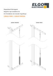
<strong>OPTICAL</strong> <strong>LENGTH</strong> <strong>AND</strong> <strong>VELOCITY</strong> <strong>SENSOR</strong><br />
<strong>OPTIPACT</strong><br />
Main features<br />
- Contact-free optical measurement principle<br />
- Two orthogonal measuring axes<br />
- Compact industrial design<br />
- Speed up to 4 m/s depending on the version<br />
- Detection of standstill<br />
- Detection of direction of motion<br />
- Tolerant against working distance variation<br />
- Self adapting to measurement object<br />
- Long-life LED illumination<br />
- Programmable via RS232 with the graphical user<br />
interface "Sensor Configurator“<br />
Applications<br />
- Distance or velocity measurement for quality<br />
control<br />
- Control of Manufacturing and Trimming processes<br />
with tape products<br />
- Positioning of Trucks, Automated Guided<br />
Vehicles (AGV), etc...<br />
- Regulation or control of continuous production,<br />
cutting and movement processes<br />
- Replacement of incremental encoders with<br />
measuring wheels through non-contact<br />
measurement<br />
Electrical Features<br />
- Polarity inversion protection<br />
- Over-voltage-peak protection<br />
- +5V or 10V..30V supply voltage selectable<br />
- 2 status LEDs<br />
Mechanical Features<br />
- Aluminium housing<br />
- Front window made of unbreakable, scratch<br />
resistant and durable plastic<br />
- Protection class IP 65<br />
FRABA INTACTON<br />
1800 East State Street, Hamilton, NJ 08609, USA<br />
Phone +1-609-750-8705, Fax +1-609-750-8703<br />
www.fraba.com , info@fraba.com
Product Overview<br />
<strong>OPTICAL</strong> <strong>LENGTH</strong> <strong>AND</strong> <strong>VELOCITY</strong> <strong>SENSOR</strong><br />
<strong>OPTIPACT</strong><br />
<strong>OPTIPACT</strong>-F1 <strong>OPTIPACT</strong> -S1 <strong>OPTIPACT</strong> -M1<br />
Velocity Range up to 1 m/s (3 ft/s) up to 4 m/s (13 ft/s) up to 2.5 m/s (8 ft/s)<br />
Working Distance 15.5 mm (0.6 in) 40 mm (1.5 in) 180 mm (7 in)<br />
Tolerance ± 10 % ± 10 % ± 6 %<br />
Measuring Uncertainty (*) < 1 % < 1 % < 0.5 %<br />
Reproducibility (*) < 0.2 % < 0.2 % < 0.2 %<br />
Best Resolution 15 µm 65 µm 30 µm<br />
Power 5 V or 10 – 30 V 5 V or 10 – 30 V 10 – 30 V<br />
Dimensions<br />
120 x 42 x 47 mm<br />
(4.7 x 1.6 x 1.8 in)<br />
120 x 42 x 47 mm<br />
(4.7 x 1.6 x 1.8 in)<br />
280 x 170 x 82 mm<br />
(11 x 6.7 x 3.2 in)<br />
Weight 0.25 kg (0.55 lb) 0.25 kg (0.55 lb) 3.5 kg (7.72 lb)<br />
Power Consumption 0.5 W 0.5 W 4 W<br />
Protection Class IP 65<br />
Temperature Range -15 to 55 °C<br />
Interfaces<br />
Incremental, RS232(**)<br />
Illumination<br />
red LED<br />
(*)Tested for a total length of 10m on red abrasive paper (P100) within the tolerence of the working distance.<br />
(**) Only when used in conjunction with the INTACTON software “Sensor Configurator”<br />
Page 2 E Info OPT F1/S1/M1 Version 6.0<br />
11/2008
<strong>OPTICAL</strong> <strong>LENGTH</strong> <strong>AND</strong> <strong>VELOCITY</strong> <strong>SENSOR</strong><br />
<strong>OPTIPACT</strong><br />
Main features 1<br />
Applications 1<br />
Electrical Features 1<br />
Mechanical Features 1<br />
Product Overview 2<br />
Technical Data 4<br />
Sensor Characteristics 4<br />
Measuring Materials 4<br />
Optics and Illumination 5<br />
Mechanical Data 5<br />
Electrical Data 6<br />
Environmental conditions 7<br />
Mechanical Drawings 8<br />
Mechanical Installation 10<br />
Electrical Connector and Pin Assignment 11<br />
Incremental Interface 12<br />
Signal Diagram 12<br />
Electrical Data 13<br />
Importance of Diagnostic LEDs 15<br />
LED Status and Meaning 15<br />
Models / Ordering Description 16<br />
Accessories and Documentation 17<br />
Page 3 E Info OPT F1/S1/M1 Version 6.0<br />
11/2008
Technical Data<br />
<strong>OPTICAL</strong> <strong>LENGTH</strong> <strong>AND</strong> <strong>VELOCITY</strong> <strong>SENSOR</strong><br />
<strong>OPTIPACT</strong><br />
Sensor Characteristics<br />
Sensor OPT-F1 OPT-S1 OPT-M1<br />
Speed-Measuring Range up to 1 m/s (3 ft/s) up to 4 m/s (13 ft/s) up to 2.5 m/s (8 ft/s)<br />
Typical Uncertainty (*) < 1 % < 1 % < 0.5 %<br />
Resolution (optical) 15 µm 65 µm 30 µm<br />
Resolution (Output)<br />
Typically 100 µm<br />
other resolutions programmable<br />
(*)Tested for a total length of 10m on red abrasive paper (P100) within the tolerence of the working distance.<br />
Measuring Materials<br />
The sensor OPT-F1 is primarily for use on very<br />
delicate surfaces, such as copy paper, cardboard,<br />
plastic, foil, shiny metal surfaces or high-grade,<br />
finely woven textiles, which do not necessarily have<br />
visible structures. It may also be programmed for<br />
coarser<br />
materials.<br />
The two sensor types, OPT-M1 and OPT-S1,<br />
however, are more suited for surfaces which<br />
through its roughness, by color or by changing<br />
reflectance, have optical structures that are<br />
easily identifiable even by the naked eye (For<br />
example, non-woven textiles, fabric, abrasive<br />
papers, etc ...)<br />
Page 4 E Info OPT F1/S1/M1 Version 6.0<br />
11/2008
<strong>OPTICAL</strong> <strong>LENGTH</strong> <strong>AND</strong> <strong>VELOCITY</strong> <strong>SENSOR</strong><br />
<strong>OPTIPACT</strong><br />
Optics and Illumination<br />
Sensor OPT-F1 OPT-S1 OPT-M1<br />
Nominal<br />
Working Distance (*)<br />
15.5 mm (0.6 in) 40 mm (1.5 in) 180 mm (7 in)<br />
Working Distance Tolerance ± 10 % ± 10 % ± 6 %<br />
Typical Measurement Area<br />
< 4 mm²<br />
(2 mm x 2 mm)<br />
< 64 mm²<br />
(8 mm x 8 mm)<br />
< 25 mm²<br />
(5 mm x 5 mm)<br />
Illumination<br />
Red LED<br />
(*) Greater working distances available upon request.<br />
Mechanical Data<br />
Sensor OPT-F1 OPT-S1 OPT-M1<br />
Housing<br />
Shock Resistance<br />
(EN 60068-2-27)<br />
Permanent Shock<br />
(EN 60028-2-29)<br />
Fatigue<br />
(EN 60068-2-6)<br />
Weight<br />
(Standard Version)<br />
Aluminum<br />
≤ 25 g (Half Sine, 6 ms) (*)<br />
≤ 10 g (Half Sine, 16 ms) (*)<br />
≤ 1 g (5 Hz ... 200 Hz, sine) (*)<br />
approx. 250 g ( 0.55 lb)<br />
approx. 3.5 kg<br />
(7.72 lb)<br />
Mounting holes M4 M6<br />
(*) Corresponding to class 3M5 (EN 60721-3-3: compliant to applications associated with significant<br />
vibrations, e.g. caused by machines or vehicles, or shocks with high density of energy, e.g. caused by heavy<br />
machines or conveyor belts)<br />
Page 5 E Info OPT F1/S1/M1 Version 6.0<br />
11/2008
<strong>OPTICAL</strong> <strong>LENGTH</strong> <strong>AND</strong> <strong>VELOCITY</strong> <strong>SENSOR</strong><br />
<strong>OPTIPACT</strong><br />
Electrical Data<br />
Sensor OPT-F1 OPT-S1 OPT-M1<br />
Power Supply<br />
(absolute values) (*)<br />
5 V or 10 - 30 V DC 10 – 30 V DC<br />
Maximum Power<br />
Consumption<br />
2.5 Watt 4 Watt<br />
Emission: EN 61000-6-4<br />
EMC<br />
Immunity: EN 61000-6-2<br />
Interface Incremental Interface, RS232 (**)<br />
Incremental Interface<br />
(Step Frequency)<br />
Using one Axis: up to 41 kHz (at four times edge count)<br />
Using two Axis:: up to 20.5 kHz (at four times edge count)<br />
Electrical Lifetime<br />
> 10 5 h<br />
(*) Supply voltage according to EN 50 178 (safety extra-low voltage).<br />
(**) RS232 is only to be used in conjunction with the "Sensor Configurator" software.<br />
Page 6 E Info OPT F1/S1/M1 Version 6.0<br />
11/2008
<strong>OPTICAL</strong> <strong>LENGTH</strong> <strong>AND</strong> <strong>VELOCITY</strong> <strong>SENSOR</strong><br />
<strong>OPTIPACT</strong><br />
Environmental conditions<br />
OperatingTemperature<br />
-15 to + 55 °C ( 8 to 120 °F)<br />
Storage Temperature<br />
- 20 to + 60 °C ( 0 to 128 °F)<br />
Relative Humidity<br />
80 % (without condensation)<br />
Protection Class (EN 60529) IP 65<br />
Page 7 E Info OPT F1/S1/M1 Version 6.0<br />
11/2008
<strong>OPTICAL</strong> <strong>LENGTH</strong> <strong>AND</strong> <strong>VELOCITY</strong> <strong>SENSOR</strong><br />
<strong>OPTIPACT</strong><br />
Mechanical Drawings<br />
OPT-F1 and OPT-S1<br />
All dimensions are in mm. Tolerances according to DIN ISO 2768-1-f.<br />
Page 8 E Info OPT F1/S1/M1 Version 6.0<br />
11/2008
<strong>OPTICAL</strong> <strong>LENGTH</strong> <strong>AND</strong> <strong>VELOCITY</strong> <strong>SENSOR</strong><br />
<strong>OPTIPACT</strong><br />
OPT-M1<br />
All dimensions are in mm. Tolerances according to DIN ISO 2768-1-f.<br />
Page 9 E Info OPT F1/S1/M1 Version 6.0<br />
11/2008
<strong>OPTICAL</strong> <strong>LENGTH</strong> <strong>AND</strong> <strong>VELOCITY</strong> <strong>SENSOR</strong><br />
<strong>OPTIPACT</strong><br />
Mechanical Installation<br />
The drawings above show the measurement of<br />
the products OPT-F1 and OPT-S1 (left) and the<br />
OPT-M1 (right). The front surface of <strong>OPTIPACT</strong><br />
must run parallel to the surface of the<br />
measurement object, to minimize the error<br />
caused due to misalignment. It is also important<br />
to make sure that the distance between the<br />
object and the front of the sensor are set to the<br />
nominal working distance of each sensor type to<br />
ensure consistency and to minimize error.<br />
The long holes for M4 (OPT-F1 and OPT-S1),<br />
and M6-bolts (OPT-M1) in the base plate of the<br />
<strong>OPTIPACT</strong> allow an appropriate orientation.<br />
The Measuring area below the camera optics is<br />
dependent on the sensor and is as follows:<br />
OPT-S1 OPT-F1 OPT-M1<br />
8 x 8 mm² 2 x 2 mm² 5 x 5 mm²<br />
The sensor should be arranged so that the<br />
object to be measured is completely covered.<br />
If the movement of the target is in a horizontal<br />
direction, we reccomend the asssembly shown<br />
above.<br />
Page 10 E Info OPT F1/S1/M1 Version 6.0<br />
11/2008
<strong>OPTICAL</strong> <strong>LENGTH</strong> <strong>AND</strong> <strong>VELOCITY</strong> <strong>SENSOR</strong><br />
<strong>OPTIPACT</strong><br />
Electrical Connector and Pin Assignment<br />
8 Pin M12-Connector male (*)<br />
Pin<br />
Signal<br />
Number<br />
1 X_A<br />
2 /X_A<br />
3 X_B<br />
4 /X_B<br />
5 + Ub_Ext<br />
6 Gnd_Ext<br />
7 RS232 Rx<br />
8 RS232 Tx<br />
8 Pin M12-Connector female (*)<br />
Pin<br />
Signal<br />
Number<br />
1 Y_A<br />
2 /Y_A<br />
3 Y_B<br />
4 /Y_B<br />
5 Digital Input 1<br />
6 Gnd_Ext<br />
7 Digital Output 1<br />
8 Digital Output 2<br />
(*) Looking at the connectors on the sensor<br />
Page 11 E Info OPT F1/S1/M1 Version 6.0<br />
11/2008
<strong>OPTICAL</strong> <strong>LENGTH</strong> <strong>AND</strong> <strong>VELOCITY</strong> <strong>SENSOR</strong><br />
<strong>OPTIPACT</strong><br />
Incremental Interface<br />
The incremental interface can be used to transmit<br />
the displacement information. Incremental length<br />
information is provided by a quadrature signal pair<br />
consisting of two square pulses, shifted in phase to<br />
each other by 90°. The direction of the movement<br />
can be deduced from the order in which the signal<br />
edges appear. In the example below an edge from<br />
signal B follows an edge from signal A with a phase<br />
shift of 90°. If the measurement object turns over to<br />
the other direction an edge of signal A will follow an<br />
edge of signal B.<br />
Signal Diagram<br />
U<br />
Signal A<br />
U<br />
Tp<br />
Period duration<br />
Signal B<br />
t<br />
Tph<br />
Smallest step size<br />
90° electrical phase shift<br />
t<br />
Signal A: Square signal A, incremental signal<br />
Signal B: Square signal B, incremental signal<br />
Tp: Period duration<br />
Tph: 90° electrical phase shift<br />
Page 12 E Info OPT F1/S1/M1 Version 6.0<br />
11/2008
<strong>OPTICAL</strong> <strong>LENGTH</strong> <strong>AND</strong> <strong>VELOCITY</strong> <strong>SENSOR</strong><br />
<strong>OPTIPACT</strong><br />
Electrical Data<br />
Sensortype OPT-F1 OPT-S1 OPT-M1<br />
Max. Output Frequency<br />
Using one Axis: up to 41 kHz (at four times edge count) (*)<br />
Using two Axis:: up to 20.5 kHz (at four times edge count) (*)<br />
Velocity Range See Picture at page 14<br />
Line Driver Version<br />
Max. Output Current<br />
Max. 25 mA<br />
Push-Pull Version<br />
Max. Output Current<br />
Max. 25 mA<br />
Max. Output Voltage<br />
Power Supply<br />
Short Circiut Poof<br />
Signal output against each other and to ground<br />
Noise immunity<br />
Balanced line transmission provides high noise immunity<br />
Paired lines Shielded and twisted pair lines are essential to maximize noise immunity.<br />
Output Driver Circuit<br />
Line Driver, RS422 compatible<br />
(*) Please divide by 4 to get the corresponding number at 1x edge count.<br />
Page 13 E Info OPT F1/S1/M1 Version 6.0<br />
11/2008
<strong>OPTICAL</strong> <strong>LENGTH</strong> <strong>AND</strong> <strong>VELOCITY</strong> <strong>SENSOR</strong><br />
<strong>OPTIPACT</strong><br />
With the setting of the finest sensor resolution, the<br />
maximum speed in the application must be<br />
considered, see graph . This graph is based on an<br />
analysis of a four times incremental edge count.<br />
Page 14 E Info OPT F1/S1/M1 Version 6.0<br />
11/2008
<strong>OPTICAL</strong> <strong>LENGTH</strong> <strong>AND</strong> <strong>VELOCITY</strong> <strong>SENSOR</strong><br />
Importance of Diagnostic LEDs<br />
<strong>OPTIPACT</strong><br />
The red and green LED shows the operation status<br />
of the <strong>OPTIPACT</strong>. The LED can be permanently lit<br />
(on), not lit ( off) or blinking. The following Table<br />
explains the different operating conditions.<br />
LED Status and Meaning<br />
Green LED Red LED Meaning<br />
On<br />
Measurement mode<br />
Blinking<br />
Configuration mode<br />
Off<br />
No supply voltage<br />
On<br />
Inability to measure<br />
Blinking<br />
Restricted measurement<br />
Off<br />
Normal operation<br />
Meaning of diagnostic LEDs in detail<br />
Green LED Red LED Meaning<br />
On Off Measurement mode, all parameters operating within specification.<br />
Blinking Off Configuration mode<br />
Off Off No supply voltage<br />
On Blinking 1x Measurement mode. Restricted measuring ability.<br />
Image brightness outside the defined range of parameter;<br />
Preventive maintenance is recommended.<br />
On Blinking 2x Measurement mode. Restricted measuring ability.<br />
Image quality operating outside the defined range of parameter;<br />
Preventive maintenance is recommended.<br />
On Blinking 3x Digital filter indicates sporadic drop outs.<br />
On Blinking 4x More than one indicator signals restricted measurement ability.<br />
Blinking Blinking Verification mode, transmission of test data without relationship to<br />
movement of measurement object.<br />
Off Blinking Transmission of image data<br />
On On Measurement mode. Measurement errors are likely. One or more<br />
parameters operating outside the defined range.<br />
Blinking On System error in configuration mode.<br />
Off On System error in measurement mode.<br />
Page 15 E Info OPT F1/S1/M1 Version 6.0<br />
11/2008
<strong>OPTICAL</strong> <strong>LENGTH</strong> <strong>AND</strong> <strong>VELOCITY</strong> <strong>SENSOR</strong><br />
Models / Ordering Description<br />
<strong>OPTIPACT</strong><br />
Bezeichnung<br />
Type Key<br />
Optipact OPT- _ 1 _ _ _ _ _ _ _ - _ _ _ _ _ 1 2 - _ _ P _ - A 0 00<br />
Model<br />
F<br />
S<br />
M<br />
Generation 1<br />
Velocity Range F: -1..+1 m/s N 0 0 1 0 0 1<br />
S: -4..+4 m/s N 0 0 4 0 0 4<br />
M: -2.5..+2.5 m/s N 0 0 2 0 0 2<br />
Working Distance (*) F: 15.5 mm 0 0 1<br />
S: 40 mm 0 0 4<br />
M: 180 mm 0 1 8<br />
Distance Deviation F: 10% 1 0<br />
S: 10% 1 0<br />
M: 3% 0 3<br />
Image sensor Internal Identifier 1<br />
Measurement axis 2 Orthogonal Axes 2<br />
Incremental RS422 Compatible 1 0<br />
Interface<br />
Push-Pull (Output Level = +U b) 2 0<br />
TTL 3 0<br />
Connection Type Connector P<br />
Supply Voltage 10 – 30 V 1<br />
5 V 2<br />
Housing Aluminium A<br />
Version 0<br />
Options without 00<br />
(*) Other working distances on request.<br />
Standard-Version = bold<br />
Page 16 E Info OPT F1/S1/M1 Version 6.0<br />
11/2008
<strong>OPTICAL</strong> <strong>LENGTH</strong> <strong>AND</strong> <strong>VELOCITY</strong> <strong>SENSOR</strong><br />
<strong>OPTIPACT</strong><br />
Accessories and Documentation<br />
Description<br />
Article number<br />
M12-male connector with 10 m cable and open end, IP 65 10005015<br />
M12-female connector with 10 m cable and open and, IP 65 10005016<br />
Configuration software (GUI) for <strong>OPTIPACT</strong> and COVIDIS (*) -<br />
<strong>OPTIPACT</strong> Manual, English (*) -<br />
These accessories are not part of the standard delivery and have to be ordered separately.<br />
(*) Visit our homepage www.intacton.com. All files can be downloaded free of charge from our<br />
homepage.<br />
We do not assume responsibility for technical inaccuracies or omissions. Specifications are subject to<br />
change without notice.<br />
Page 17 E Info OPT F1/S1/M1 Version 6.0<br />
11/2008