Falcon 9 Launch Vehicle Payload User's Guide - SpaceX
Falcon 9 Launch Vehicle Payload User's Guide - SpaceX
Falcon 9 Launch Vehicle Payload User's Guide - SpaceX

Create successful ePaper yourself
Turn your PDF publications into a flip-book with our unique Google optimized e-Paper software.
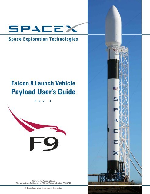
<strong>Falcon</strong> 9 <strong>Launch</strong> <strong>Vehicle</strong><br />
<strong>Payload</strong> User’s <strong>Guide</strong><br />
R e v 1<br />
Approved for Public Release.<br />
Cleared for Open Publication by Office of Security Review. 09-S-0347<br />
© Space Exploration Technologies Corporation
Table of Contents<br />
<strong>Falcon</strong> 9 User’s <strong>Guide</strong><br />
Table of Contents 2<br />
1. Introduction 4<br />
1.1. Revision History 4<br />
1.2. Purpose 4<br />
1.3. Company Description 4<br />
1.4. <strong>Falcon</strong> Program Overview 5<br />
1.5. Mission Management 5<br />
1.6. Key Customer Advantages 5<br />
1.6.1. Reliability 5<br />
1.6.2. Pricing 7<br />
2. <strong>Vehicle</strong> Overview 8<br />
2.1. <strong>Falcon</strong> 9 <strong>Launch</strong> <strong>Vehicle</strong>s 8<br />
2.1.1. Structure and Propulsion 8<br />
2.1.2. Avionics, Guidance/Navigation/Control, Flight Termination<br />
Systems 8<br />
2.2. <strong>Vehicle</strong> Axes/Attitude Definitions 11<br />
3. Facilities Overview 12<br />
3.1. Headquarters – Hawthorne, CA 12<br />
3.2. Space <strong>Launch</strong> Complex 40, Cape Canaveral Air Force Station, Florida 12<br />
3.3. Space <strong>Launch</strong> Complex ‐ 4 East, Vandenberg Air Force Base (VAFB),<br />
California 15<br />
3.4. U.S. Army Kwajalein Atoll, Marshall Islands 16<br />
3.5. Test Facility ‐ Central Texas 17<br />
3.6. Government Outreach and Legal Affairs‐‐Washington, DC 17<br />
4. General Performance Capability 18<br />
4.1. Performance Capability 18<br />
4.1.1. Low Earth Orbit 19<br />
4.1.2. Polar 20<br />
4.1.3. Sun Synchronous 21<br />
4.1.4. C3 – Escape Velocity 22<br />
4.1.5. Geosynchronous Transfer Orbit (Cape Canaveral) 23<br />
4.1.6. Geosynchronous Transfer Orbit (Kwajalein) 24<br />
4.1.7. Geosynchronous Transfer Orbit (Delta‐Velocity To Go) [Cape] 25<br />
4.1.8. Geosynchronous Transfer Orbit (Delta‐Velocity To Go)<br />
[Kwajalein] 26<br />
4.2. Sample Mission Profiles 27<br />
4.3. Mass Properties 29<br />
4.4. Separation Accuracy 29<br />
4.5. Mission Accuracy Data 29<br />
SCM 2008‐010 Rev. 1 Copyright ‐‐ <strong>SpaceX</strong> 2009 2
<strong>Falcon</strong> 9 User’s <strong>Guide</strong><br />
5. General <strong>Payload</strong> Information 30<br />
5.1. <strong>Payload</strong> Fairing 30<br />
5.1.1. General Description 30<br />
5.1.2. <strong>Falcon</strong> 9 Fairing 30<br />
5.1.3. <strong>Payload</strong> Separation 31<br />
5.1.4. Collision Avoidance 31<br />
5.2. <strong>Payload</strong> Environments 31<br />
5.2.1. Transportation Environments 31<br />
5.2.2. Humidity, Cleanliness and Thermal Control 32<br />
5.2.3. <strong>Launch</strong> and Flight Environments 32<br />
5.3. <strong>Payload</strong> Interfaces 40<br />
5.3.1. <strong>Falcon</strong> 9 <strong>Payload</strong> Attach Fittings 41<br />
5.3.2. Test Fittings and Fitcheck Policy 43<br />
5.3.3. Electrical Interfaces 43<br />
5.4. <strong>Payload</strong> Integration 46<br />
5.4.1. Integration Schedule 46<br />
5.4.2. Documentation Requirements 50<br />
5.4.3. Standard Services 50<br />
5.4.4. Non‐standard Services 51<br />
6. <strong>Launch</strong> Operations 52<br />
6.1. <strong>Launch</strong> Control Organization 53<br />
6.2. Spacecraft Transport to <strong>Launch</strong> Site 55<br />
6.2.1. Processing Services and Equipment 55<br />
6.3. Plans and Schedules 57<br />
6.3.1. Mission Integration Plan 59<br />
6.3.2. <strong>Launch</strong> <strong>Vehicle</strong> Schedules 60<br />
7. Safety 61<br />
7.1. Safety Requirements 61<br />
7.2. Hazardous Systems and Operations 61<br />
7.3. Waivers 61<br />
8. <strong>Payload</strong> Questionnaire 62<br />
9. Quick Reference 63<br />
9.1. List of Figures 63<br />
9.2. List of Tables 64<br />
9.3. List of Acronyms 64<br />
SCM 2008‐010 Rev. 1 Copyright ‐‐ <strong>SpaceX</strong> 2009 3
1. Introduction<br />
1.1. Revision History<br />
This is the first publicly available version of the <strong>Falcon</strong> 9 <strong>Launch</strong> <strong>Vehicle</strong> <strong>User's</strong> <strong>Guide</strong>.<br />
<strong>Falcon</strong> 9 User’s <strong>Guide</strong><br />
1.2. Purpose<br />
The <strong>Falcon</strong> 9 User’s <strong>Guide</strong> is a planning document provided for potential and current customers<br />
of Space Exploration Technologies (<strong>SpaceX</strong>). This document is not intended for detailed design<br />
use. Data for detailed design purposes will be exchanged directly between a <strong>SpaceX</strong> Mission<br />
Manager and the <strong>Payload</strong> Provider. This <strong>User's</strong> <strong>Guide</strong> highlights the <strong>Falcon</strong> 9 Block 2 launch<br />
vehicle and launch service. The Block 2 launch vehicle offers improved mass‐to‐orbit<br />
performance when compared to the <strong>Falcon</strong> 9 Block 1. Specific differences between Block 1 and<br />
Block 2 will be identified, when appropriate. Performance and environments information are<br />
based upon <strong>Falcon</strong> 9 requirements and analyses, but are not yet validated by flight data.<br />
1.3. Company Description<br />
In an era when most technology‐based products follow a path of ever‐increasing capability and<br />
reliability while simultaneously reducing costs, today’s launch vehicles are little changed from<br />
those of 40 years ago. <strong>SpaceX</strong> is changing this paradigm with a family of launch vehicles which<br />
will ultimately reduce the cost and increase the reliability of access to space. Coupled with the<br />
newly emerging market for private and commercial space transport, this new model will re‐<br />
ignite humanity's efforts to explore and develop space.<br />
<strong>SpaceX</strong> was founded on the philosophy that simplicity, reliability, and low‐cost are closely<br />
coupled. We approach all elements of launch services with a focus on simplicity to both<br />
increase reliability and lower cost. The <strong>SpaceX</strong> corporate structure is flat and business<br />
processes are lean, resulting in both fast decision making and delivery. <strong>SpaceX</strong> products are<br />
designed to require low infrastructure facilities (production and launch) with low maintenance<br />
overhead, while vehicle design teams are co‐located with production and quality assurance<br />
staff to tighten the critical feedback loop. The result is highly producible and low cost designs<br />
with quality imbedded. To better understand how <strong>SpaceX</strong> can achieve low cost without<br />
sacrificing reliability, please see the Frequently Asked Questions at www.spacex.com.<br />
Established in 2002 by Elon Musk, the founder of PayPal and the Zip2 Corporation, <strong>SpaceX</strong> has<br />
already developed a light lift launch vehicle, the <strong>Falcon</strong> 1, nearly completed development of the<br />
<strong>Falcon</strong> 9, and developed state of the art testing and launch locations.<br />
In addition, NASA has selected the <strong>SpaceX</strong> <strong>Falcon</strong> 9 launch vehicle and Dragon spacecraft for<br />
the International Space Station (ISS) Cargo Resupply Services (CRS) contract award. The<br />
contract is for a guaranteed minimum of 20,000 kg to be carried to the International Space<br />
Station. The firm contracted value is $1.6 billion and NASA may elect to order additional<br />
missions for a cumulative total contract value of up to $3.1 billion. <strong>SpaceX</strong> is on sound financial<br />
footing as we move towards volume commercial launches.<br />
SCM 2008‐010 Rev. 1 Copyright ‐‐ <strong>SpaceX</strong> 2009 4
<strong>Falcon</strong> 9 User’s <strong>Guide</strong><br />
Our design and manufacturing facilities are conveniently located near the Los Angeles<br />
International airport. This location also allows the company to leverage the deep and rich<br />
aerospace talent pool available in Southern California. The <strong>SpaceX</strong> state‐of‐the‐art propulsion<br />
and structural test facilities are located in Central Texas.<br />
1.4. <strong>Falcon</strong> Program Overview<br />
Drawing upon a rich history of prior launch vehicle and engine programs, <strong>SpaceX</strong> is privately<br />
developing the <strong>Falcon</strong> family of rockets from the ground up, including main and upper‐stage<br />
engines, the cryogenic tank structure, avionics, guidance & control software and ground<br />
support equipment.<br />
With the <strong>Falcon</strong> 1, <strong>Falcon</strong> 1e, <strong>Falcon</strong> 9 and <strong>Falcon</strong> 9 Heavy launch vehicles, <strong>SpaceX</strong> is able to<br />
offer a full spectrum of light, medium and heavy lift launch capabilities to our customers. We<br />
are able to deliver spacecraft into any inclination and altitude, from low Earth orbit (LEO) to<br />
geosynchronous orbit (GEO) to planetary missions. The <strong>Falcon</strong> 9 and <strong>Falcon</strong> 9 Heavy are the<br />
only US launch vehicles with true engine‐out reliability. They are also designed such that all<br />
stages are reusable, making them the world's first fully reusable launch vehicles. The Dragon<br />
crew and cargo capsule, in conjunction with our <strong>Falcon</strong> 9, have been selected by NASA to<br />
provide efficient and reliable transport of cargo and potentially crew to the International Space<br />
Station (ISS) and other LEO destinations.<br />
1.5. Mission Management<br />
To facilitate and streamline communication, each customer works with a single <strong>SpaceX</strong> contact,<br />
a Mission Manager. The Mission Manager works closely with the customer, <strong>SpaceX</strong> technical<br />
execution staff and all associated licensing agencies in order to achieve a successful mission.<br />
Specifically, the <strong>SpaceX</strong> Mission Manager is responsible for coordinating mission integration<br />
analysis and documentation deliverables, planning integration meetings and reports, and<br />
coordinating all integration and test activities associated with the mission.<br />
The Mission Manager will also facilitate customer insight during the launch campaign. Though<br />
the launch operations team is ultimately responsible for customer hardware and associated<br />
Ground Support Equipment (GSE), the Mission Manager will coordinate all launch site activities<br />
to ensure customer satisfaction during this critical phase.<br />
1.6. Key Customer Advantages<br />
1.6.1. Reliability<br />
The vast majority of launch vehicle failures in the past two decades can be attributed to three<br />
causes: engine, avionics and stage separation failures. An analysis by Aerospace Corporation 1<br />
showed that 91% of known failures can be attributed to those subsystems.<br />
1<br />
http://www.aero.org/publications/crosslink/winter2001/03.html. A hard copy of this reference can be made<br />
available upon request.<br />
SCM 2008‐010 Rev. 1 Copyright ‐‐ <strong>SpaceX</strong> 2009 5
<strong>Falcon</strong> 9 User’s <strong>Guide</strong><br />
With this in mind, <strong>Falcon</strong> 9 launch vehicles are designed for high reliability starting at the<br />
architectural level and incorporate the flight‐proven design and features of the <strong>Falcon</strong> 1 launch<br />
vehicle. Some of the significant contributors to reliability include:<br />
• Robust design margins<br />
<strong>Falcon</strong> 9 is designed with the goal of carrying humans into space aboard the <strong>SpaceX</strong><br />
Dragon capsule. This goal drives the initial design of <strong>Falcon</strong> 9 through the incorporation<br />
of increased factors of safety (1.4 versus the traditional 1.25 for uncrewed flight).<br />
<strong>Payload</strong> customers using the <strong>Falcon</strong> 9 can take advantage of this increased design<br />
robustness. The first and second stages are also designed to be recovered and reused,<br />
and therefore, must have significantly higher margins than an expendable stage. This<br />
also provides a unique opportunity to examine recovered hardware and assess design<br />
and material selection in order to continually improve <strong>Falcon</strong> 9.<br />
• Propulsion and separation event design<br />
The heart of <strong>Falcon</strong> 9 propulsion is the Merlin 1C liquid propellant rocket engine. The<br />
Merlin engine features a robust, reliable turbopump design incorporating a single shaft<br />
for both the liquid oxygen and fuel pumps, and a gas generator cycle versus the more<br />
complex staged combustion. The regeneratively‐cooled thrust chamber uses a milled<br />
copper alloy liner chamber that provides large margins on heat flux. In addition, the<br />
pintle injector was selected for its inherent combustion stability. As a part of our launch<br />
operations, we hold the first stage after ignition and monitor engine prior to release to<br />
watch engine trends. If an off‐nominal condition exists, an autonomous abort is<br />
conducted. This helps prevent an engine performance issue from causing a failure in<br />
flight. <strong>Falcon</strong> 9 makes use of ten Merlin 1C engines on each vehicle (nine on the first<br />
stage, one on the second stage) resulting in high volume engine production, which<br />
results in much higher quality through process control. Flying ten engines on each<br />
mission also builds substantial heritage quickly. Importantly, by employing nine first<br />
stage engines, <strong>SpaceX</strong> debuts the world’s first Evolved Expendable <strong>Launch</strong> <strong>Vehicle</strong><br />
(EELV)‐class launch vehicle with engine‐out capability through much of first stage flight.<br />
With the qualification and first flight units in build and several domestic and<br />
international purchased flights currently manifested, <strong>Falcon</strong> 9 is an ideal workhorse for<br />
payload customers.<br />
<strong>SpaceX</strong> has also minimized the number of stages (2) to minimize separation events. The<br />
separation system between the first and second stages does not incorporate electro‐<br />
explosive devices, instead relying upon a pneumatic release and separation system that<br />
allows for acceptance testing of the actual flight hardware. This is not possible with a<br />
traditional explosive‐based separation system.<br />
• Failure mode minimization<br />
<strong>SpaceX</strong> minimized the number of failure modes by minimizing the number of separate<br />
subsystems. The first stage thrust vector control (TVC) system makes use of pressurized<br />
SCM 2008‐010 Rev. 1 Copyright ‐‐ <strong>SpaceX</strong> 2009 6
<strong>Falcon</strong> 9 User’s <strong>Guide</strong><br />
rocket‐ grade kerosene (RP‐1). The engine pulls from the high pressure RP‐1 side of the<br />
pump to power the TVC. This eliminates the separate hydraulic system. In addition it<br />
eliminates the failure mode associated with running out of pressurized fluid. Also, the<br />
avionics and guidance/navigation/control systems are designed with single fault<br />
tolerance, supporting the ability of <strong>Falcon</strong> 9 to be human rated.<br />
• Rigorous testing<br />
In addition to <strong>SpaceX</strong>’s unique design decisions, <strong>Falcon</strong> 9 will undergo an exhaustive<br />
series of tests from the component to the vehicle system level. This includes<br />
component level qualification and workmanship testing, structures load and proof<br />
testing, flight system and propulsion subsystem level testing, full first and second stage<br />
testing up to full system testing, including stage static firings at the test and launch sites<br />
(as appropriate). In addition to testing environmental extremes (plus margin), all<br />
hardware is tested to account for off‐nominal conditions. For example, both stage and<br />
fairing separation tests require testing for off‐nominal cases with respect to geometrical<br />
misalignment, anomalous pyro timing and sequencing.<br />
A major contributor to a reliable system is its operations. To support robust launch operations,<br />
the <strong>SpaceX</strong> launch countdown is fully automated with thousands of checks made prior to<br />
vehicle release. After first stage ignition, the vehicle is not released until the first stage engines<br />
are confirmed to be operating normally. A safe shutdown is executed, should any off nominal<br />
conditions be detected. <strong>Falcon</strong> 9 benefits from the design and operations concepts established<br />
for and proven with the successful <strong>Falcon</strong> 1 program.<br />
1.6.2. Pricing<br />
The standard price per launch for <strong>Falcon</strong> 9 <strong>Launch</strong> <strong>Vehicle</strong>s can be found here 2 . Pricing includes<br />
range, standard payload integration and third party liability insurance. Please see Section 5.4<br />
for a description of the standard services. Non‐standard services are also available. If non‐<br />
standard services are required, please identify these in the <strong>Payload</strong> Questionnaire found in<br />
Section 8 of this <strong>Guide</strong>.<br />
2 http://www.spacex.com/falcon9.php#pricing_and_performance.<br />
SCM 2008‐010 Rev. 1 Copyright ‐‐ <strong>SpaceX</strong> 2009 7
2. <strong>Vehicle</strong> Overview<br />
<strong>Falcon</strong> 9 User’s <strong>Guide</strong><br />
2.1. <strong>Falcon</strong> 9 <strong>Launch</strong> <strong>Vehicle</strong>s<br />
<strong>Falcon</strong> 9 <strong>Launch</strong> <strong>Vehicle</strong>s are designed to provide breakthrough advances in reliability, cost, and<br />
time to launch. The primary design driver is, and will remain, reliability. <strong>SpaceX</strong> recognizes that<br />
nothing is more important than getting a customer’s payload safely to its intended destination.<br />
The initial flights of the <strong>Falcon</strong> 9, currently planned in 2009 and 2010, use the <strong>Falcon</strong> 9 Block 1.<br />
Beginning in late 2010/early 2011, <strong>SpaceX</strong> will begin launching the <strong>Falcon</strong> 9 Block 2. Block 2<br />
features increased engine thrust, decreased launch vehicle dry mass, and increased propellant<br />
load ‐ combined with lessons learned from the flights of the <strong>Falcon</strong> 9 Block 1. This results in<br />
increased mass‐to‐orbit performance for the <strong>Falcon</strong> 9 Block 2 when compared with Block 1<br />
performance. This performance is shown in the <strong>Falcon</strong> 9 performance tables presented later in<br />
this document.<br />
2.1.1. Structure and Propulsion<br />
Like <strong>Falcon</strong> 1, <strong>Falcon</strong> 9 is a two‐stage, liquid oxygen (LOX) and rocket grade kerosene (RP‐1)<br />
powered launch vehicle. It uses the same Merlin engines, structural architecture (with a wider<br />
diameter), and launch control system.<br />
The <strong>Falcon</strong> 9 propellant tank walls and domes are made from an aluminum lithium alloy.<br />
<strong>SpaceX</strong> uses an all friction stir welded tank, the highest strength and most reliable welding<br />
technique available. Like <strong>Falcon</strong> 1, the <strong>Falcon</strong> 9 interstage, which connects the upper and lower<br />
stages, is a carbon fiber aluminum core composite structure. The separation system is a larger<br />
version of the pneumatic pushers used on <strong>Falcon</strong> 1.<br />
Nine <strong>SpaceX</strong> Merlin engines power the <strong>Falcon</strong> 9 first stage with 125,000 lbf sea level thrust per<br />
engine, for a total thrust on liftoff of just over 1.1 million lbf. After engine start, <strong>Falcon</strong> 9 is held<br />
down until all vehicle systems are verified as functioning normally before release for liftoff.<br />
The second stage tank of <strong>Falcon</strong> 9 is simply a shorter version of the first stage tank and uses<br />
most of the same tooling, material and manufacturing techniques. This results in significant cost<br />
savings in vehicle production.<br />
A single Merlin engine powers the <strong>Falcon</strong> 9 upper stage with an expansion ratio of 117:1 and a<br />
nominal burn time of 345 seconds. For added reliability of restart, the engine has dual<br />
redundant pyrophoric igniters (TEA‐TEB).<br />
The <strong>Falcon</strong> 9 fairing is 17 ft (5.2 m) in diameter.<br />
2.1.2. Avionics, Guidance/Navigation/Control, Flight Termination Systems<br />
<strong>Falcon</strong> 9 vehicle avionics features a single‐fault tolerant architecture and has been designed<br />
with a view towards human‐rating requirements in order to allow future qualification for<br />
SCM 2008‐010 Rev. 1 Copyright ‐‐ <strong>SpaceX</strong> 2009 8
<strong>Falcon</strong> 9 User’s <strong>Guide</strong><br />
crewed launch capability. Avionics include rugged flight computers, GPS receivers, inertial<br />
measurement units, <strong>SpaceX</strong>‐designed and manufactured controllers for vehicle control<br />
(propulsion, valve, pressurization, separation, and payload interfaces), and a C‐Band<br />
transponder for Range Safety tracking. <strong>Falcon</strong> 9 transmits telemetry from both the first and<br />
second stages, even after separation of the stages. S‐band transmitters are used to transmit<br />
telemetry and video to the ground.<br />
The guidance and navigation algorithms for <strong>Falcon</strong> 9 launch vehicles have been heavily<br />
influenced by the algorithms used on other launch vehicles, including <strong>Falcon</strong> 1. The guidance<br />
system takes into account the loss of an engine during first stage burn and adjusts the targeted<br />
trajectory accordingly. This mix of explicit and perturbation guidance schemes was selected in<br />
order to generate a smooth, computationally simple trajectory while maintaining orbital<br />
insertion accuracies.<br />
The <strong>Falcon</strong> 9 launch vehicle is equipped with a standard flight termination system. This system<br />
includes two redundant strings of command receiver and encoder, batteries, safe and arm<br />
devices, and ordnance in the event of an anomaly in flight.<br />
SCM 2008‐010 Rev. 1 Copyright ‐‐ <strong>SpaceX</strong> 2009 9
Table 2‐1 ‐ <strong>Falcon</strong> 9 <strong>Launch</strong> <strong>Vehicle</strong> (Block 2) Dimensions and Characteristics<br />
<strong>Falcon</strong> 9 User’s <strong>Guide</strong><br />
Characteristic<br />
Structure<br />
Stage 1 Stage 2<br />
Length 180 feet [55m] (both stages with fairing & interstage)<br />
Diameter 12 feet [3.66m]<br />
Type LOX tank ‐ monococque; Fuel<br />
tank ‐ stringer and ring frame<br />
Monococque<br />
Material<br />
Propulsion<br />
Aluminum lithium Aluminum lithium<br />
Engine Type Liquid, gas generator Liquid, gas generator<br />
Engine Manufacturer <strong>SpaceX</strong> <strong>SpaceX</strong><br />
Engine Designation Merlin 1C Merlin Vacuum<br />
Number of engines 9 1<br />
Propellant Liquid oxygen/Kerosene (RP‐1) Liquid oxygen/Kerosene (RP‐1)<br />
Thrust 1,125,000 lbf (sea level) [5MN] 100,000 lbf (vacuum) [445kN]<br />
Propellant feed system Turbopump Turbopump<br />
Throttle capability No Yes (60‐100%)<br />
Restart capability No Yes ‐ 2 restarts<br />
Tank pressurization<br />
Thrust Vector Control<br />
Heated helium Heated helium<br />
Pitch, Yaw Gimbaled engines Gimbaled engine<br />
Roll<br />
Reaction Control System<br />
Gimbaled engines Turbine exhaust duct (gimbal)<br />
Propellant Not applicable Monomethyl hydrazine,<br />
nitrogen tetroxide<br />
Thrusters Not applicable Draco (4)<br />
Thrust<br />
Staging<br />
Not applicable 90 lbf [400N] each<br />
Nominal burn time 170 sec 354 sec<br />
Shutdown process Commanded shutdown Commanded shutdown<br />
Stage separation system Pneumatically actuated<br />
mechanical collets<br />
Not applicable<br />
SCM 2008‐010 Rev. 1 Copyright ‐‐ <strong>SpaceX</strong> 2009 10
2.2. <strong>Vehicle</strong> Axes/Attitude Definitions<br />
C Band<br />
90 deg<br />
S ‐Band<br />
60 deg<br />
UHF<br />
120 deg<br />
True North<br />
(10 deg app .)<br />
Positive Clocking<br />
Angle<br />
TAA ‐3C<br />
(Telemetry )<br />
+Z (0 deg)<br />
FPS 16 (Radar )<br />
FTS<br />
Transmitter<br />
JD Missile Tracking<br />
Annex<br />
Figure 2‐1 ‐ <strong>Falcon</strong> 9 launch vehicle layout and coordinate system<br />
SCM 2008‐010 Rev. 1 Copyright ‐‐ <strong>SpaceX</strong>. 2009<br />
Q I<br />
Transporter /<br />
Errector<br />
9<br />
8<br />
7<br />
6<br />
Q IV<br />
5<br />
4<br />
Q II<br />
Q III<br />
3<br />
2<br />
1<br />
Notes<br />
‐ <strong>Vehicle</strong> as seen from above<br />
‐ <strong>Vehicle</strong> coordinate frame as shown , with the X<br />
axis being the vehicle longitudinal axis , positive<br />
forward . This coordinate frame is aligned with<br />
the Erector<br />
30 . 8°<br />
UHF<br />
300 deg<br />
C ‐Band 270 deg<br />
+Y<br />
S ‐Band 240 deg<br />
Fairing Split Line<br />
292 .5 deg<br />
<strong>Falcon</strong> 9 User’s <strong>Guide</strong><br />
11
3. Facilities Overview<br />
<strong>Falcon</strong> 9 User’s <strong>Guide</strong><br />
3.1. Headquarters – Hawthorne, CA<br />
<strong>SpaceX</strong> headquarters are conveniently located in Hawthorne, CA, a few miles inland from Los<br />
Angeles International Airport (LAX). The 550,000+ square foot (5.1 hectares) design and<br />
manufacturing facility ranks among the largest manufacturing facilities in California. Two<br />
complete <strong>Falcon</strong> 9s will fit end‐to‐end along the short length of the building. For production,<br />
there are three <strong>Falcon</strong> 1 lines, three parallel <strong>Falcon</strong> 9 lines, nearly two dozen Merlin engine<br />
assembly stations, and Dragon capsule production areas. Potential customers are encouraged<br />
to arrange a tour when in the Los Angeles area. Map and Directions.<br />
Figure 3‐1‐ Hawthorne, California Headquarters<br />
3.2. Space <strong>Launch</strong> Complex 40, Cape Canaveral Air Force Station, Florida<br />
<strong>SpaceX</strong> has a <strong>Falcon</strong> 9 launch site on Cape Canaveral Air Force Station (CCAFS). The launch site<br />
is Space <strong>Launch</strong> Complex 40 (SLC‐40), former home of the Titan IV heavy lift rockets. <strong>SpaceX</strong><br />
facilities at SLC‐40 include a hangar, propellant/pressurant storage and supply areas, launch<br />
pad, and lightning towers. Adjacent to the launch complex is the <strong>SpaceX</strong> administrative office<br />
facility. <strong>SpaceX</strong> launch operations are managed from the <strong>Launch</strong> Control Center, located at the<br />
south entrance to CCAFS. A general layout of the launch facilities is presented in the following<br />
figures.<br />
Figure 3‐2 ‐ <strong>Launch</strong> Complex 40 at Cape Canaveral Air Force Station (CCAFS), Florida<br />
SCM 2008‐010 Rev. 1 Copyright ‐‐ <strong>SpaceX</strong> 2009 12
Figure 3‐3 ‐ Space <strong>Launch</strong> Complex 40 Instrumentation Bay location<br />
<strong>Falcon</strong> 9 User’s <strong>Guide</strong><br />
SCM 2008‐010 Rev. 1 Copyright ‐‐ <strong>SpaceX</strong> 2009 13
Figure 3‐4 ‐ Space <strong>Launch</strong> Complex 40 Hangar layout<br />
<strong>Falcon</strong> 9 User’s <strong>Guide</strong><br />
SCM 2008‐010 Rev. 1 Copyright ‐‐ <strong>SpaceX</strong> 2009 14
<strong>Falcon</strong> 9 User’s <strong>Guide</strong><br />
3.3. Space <strong>Launch</strong> Complex ‐ 4 East, Vandenberg Air Force Base (VAFB), California<br />
<strong>SpaceX</strong> plans to establish a launch facility at Vandenberg Air Force Base (VAFB) in central<br />
California to meet customer needs for polar and sun‐synchronous capability. <strong>SpaceX</strong>’s<br />
headquarters, manufacturing and production facility is located in the Los Angeles area, within<br />
driving distance or a short flight to VAFB. <strong>SpaceX</strong> has previously worked with the Range at<br />
VAFB on <strong>Falcon</strong> 1 facilities, including conducting a static fire at SLC‐3 West in 2005. The<br />
candidate launch site, pending discussions with the U.S. Air Force, would be at Space <strong>Launch</strong><br />
Complex 4 East (SLC‐4E). The design of the <strong>Falcon</strong> 9 launch site at VAFB will mirror the facilities<br />
and operations implemented at the Cape Canaveral launch site.<br />
Figure 3‐5 ‐ SLC‐4 East, VAFB<br />
SCM 2008‐010 Rev. 1 Copyright ‐‐ <strong>SpaceX</strong> 2009 15
<strong>Falcon</strong> 9 User’s <strong>Guide</strong><br />
3.4. U.S. Army Kwajalein Atoll, Marshall Islands<br />
<strong>SpaceX</strong> has an operational <strong>Falcon</strong> 1 launch site at the Kwajalein Atoll, about 2500 miles<br />
southwest of Hawaii. The <strong>Falcon</strong> 1 launch facilities are situated on Omelek Island, part of the<br />
Ronald Reagan Ballistic Missile Defense Test Site (RTS) at United States Army Kwajalein Atoll<br />
(USAKA). The location and a general layout of the launch facility are presented in Figure 3‐6.<br />
<strong>SpaceX</strong> is evaluating establishing a launch facility for <strong>Falcon</strong> 9 at Kwajalein that would provide<br />
superior performance to geosynchronous transfer orbit as well as high‐inclination orbits.<br />
Figure 3‐6 ‐ <strong>Falcon</strong> 1 launch site, Kwajalein Atoll<br />
SCM 2008‐010 Rev. 1 Copyright ‐‐ <strong>SpaceX</strong> 2009 16
<strong>Falcon</strong> 9 User’s <strong>Guide</strong><br />
3.5. Test Facility ‐ Central Texas<br />
Structural and propulsion tests are conducted at the rapidly growing and expanding test site<br />
located in McGregor, Texas, just west of Waco. Conveniently located 2 hours from both Austin<br />
and Dallas, the site is staffed with test engineers, technicians and management personnel.<br />
During preparation and testing, the site also plays host to personnel from the California<br />
headquarters who supplement the Texas team.<br />
Figure 3‐7 ‐ <strong>SpaceX</strong>’s Texas Test Facility<br />
3.6. Government Outreach and Legal Affairs‐‐Washington, DC<br />
<strong>SpaceX</strong>’s government outreach and licensing team is located in Washington, DC.<br />
SCM 2008‐010 Rev. 1 Copyright ‐‐ <strong>SpaceX</strong> 2009 17
4. General Performance Capability<br />
<strong>Falcon</strong> 9 User’s <strong>Guide</strong><br />
4.1. Performance Capability<br />
The <strong>Falcon</strong> 9 launch vehicle performance presented in the following tables and figures is for the<br />
Block 2 (see paragraph 2.1.2 for details). The performance shown is the maximum capability of<br />
the <strong>Falcon</strong> 9 Block 2 with margin withheld by <strong>SpaceX</strong> to ensure mission success. Please note<br />
typical payloads in the <strong>Falcon</strong> 9 class typically below 15000 lbs (6800 kg). Potential customers<br />
should contact <strong>SpaceX</strong> if they contemplate flying extra‐heavy payloads or using most of the<br />
listed performance of the <strong>Falcon</strong> 9.<br />
For reference, the following is a list of tables and figures in this section:<br />
Section 4.1 List of Figures<br />
Figure 4‐1 ‐ <strong>Falcon</strong> 9 Block 2 Performance to Low Earth Orbit (Cape Canaveral) ........................ 19<br />
Figure 4‐2 ‐ <strong>Falcon</strong> 9 Block 2 Performance ‐ Circular Polar Orbit ................................................. 20<br />
Figure 4‐3 ‐ <strong>Falcon</strong> 9 Block 2 Performance ‐ Sun Synchronous Orbit ........................................... 21<br />
Figure 4‐4 ‐ <strong>Falcon</strong> 9 Block 2 Performance ‐ Escape Velocity (Cape Canaveral) .......................... 22<br />
Figure 4‐5 ‐ <strong>Falcon</strong> 9 Block 2 Performance to Geosynchronous Transfer Orbit ........................... 23<br />
Figure 4‐6 ‐ <strong>Falcon</strong> 9 Block 2 Performance to Geosynchronous Transfer Orbit (Kwajalein) ........ 24<br />
Figure 4‐7 ‐ Geosynchronous Transfer Orbit (Delta‐Velocity to Go) from Cape .......................... 25<br />
Figure 4‐8 ‐ Geosynchronous Transfer Orbit (Delta‐Velocity to Go) from Kwaj .......................... 26<br />
Figure 4‐9 ‐ <strong>Falcon</strong> 9 Sample Flight Profile, Geosynchronous Transfer Orbit Mission ................. 27<br />
Section 4.1 List of Tables<br />
Table 4‐1 ‐ <strong>Falcon</strong> 9 Block 2 Performance to Low Earth Orbit (Cape Canaveral) ......................... 19<br />
Table 4‐2 <strong>Falcon</strong> 9 Block 2 Performance ‐ Circular Polar Orbit .................................................... 20<br />
Table 4‐3 ‐ <strong>Falcon</strong> 9 Block 2 Performance ‐ Sun Synchronous Orbit ............................................ 21<br />
Table 4‐4 ‐ <strong>Falcon</strong> 9 Block 2 Performance ‐ Escape Velocity (Cape Canaveral) ............................ 22<br />
Table 4‐5 ‐ <strong>Falcon</strong> 9 Block 2 Performance to Geosynchronous Transfer Orbit ............................ 23<br />
Table 4‐6 ‐ <strong>Falcon</strong> 9 Block 2 Performance to Geosynchronous Transfer Orbit (Kwajalein) ......... 24<br />
Table 4‐7 ‐ Geosynchronous Transfer Orbit (Delta‐Velocity to Go) from Cape ........................... 25<br />
Table 4‐8 ‐ Geosynchronous Transfer Orbit (Delta‐Velocity to Go) from Kwaj ............................ 26<br />
Table 4‐9 ‐ <strong>Falcon</strong> 9 Sample Flight Timeline, Geosynchronous Transfer Orbit Mission ............... 28<br />
SCM 2008‐010 Rev. 1 Copyright ‐‐ <strong>SpaceX</strong> 2009 18
4.1.1. Low Earth Orbit<br />
<strong>Payload</strong> Mass (kg)<br />
12000<br />
10000<br />
8000<br />
6000<br />
4000<br />
2000<br />
0<br />
Circular Orbit<br />
Altitude (km)<br />
<strong>Falcon</strong> 9 User’s <strong>Guide</strong><br />
0 500 1000 1500 2000 2500<br />
Circular Altitude (km)<br />
51.6 deg 38 deg 28.5 deg<br />
Figure 4‐1 ‐ <strong>Falcon</strong> 9 Block 2 Performance to Low Earth Orbit (Cape Canaveral)<br />
Table 4‐1 ‐ <strong>Falcon</strong> 9 Block 2 Performance to Low Earth Orbit (Cape Canaveral)<br />
<strong>Payload</strong> Mass (kg)<br />
Inclination (degrees)<br />
Circular Orbit<br />
<strong>Payload</strong> Mass (kg)<br />
Inclination (degrees)<br />
28.5 38 51.6 Altitude (km)<br />
28.5 38 51.6<br />
200 10454 10221 9823 1100 8500 8303 7970<br />
300 10202 9975 9586 1200 8320 8127 7799<br />
400 9953 9737 9358 1300 8147 7957 7635<br />
500 9727 9508 9138 1400 7979 7792 7475<br />
600 9503 9289 8924 1500 7817 7633 7320<br />
700 9287 9076 8719 1600 7662 7480 7172<br />
800 9080 8872 8522 1700 7510 7330 7028<br />
900 8879 8676 8331 1800 7364 7187 6888<br />
1000 8687 8486 8148 1900 7221 7048 6753<br />
2000 7085 6913 6622<br />
SCM 2008‐010 Rev. 1 Copyright ‐‐ <strong>SpaceX</strong> 2009 19
4.1.2. Polar<br />
<strong>Payload</strong> Mass (kg)<br />
12000<br />
10000<br />
8000<br />
6000<br />
4000<br />
2000<br />
0<br />
Circular Orbit<br />
Altitude (km)<br />
<strong>Falcon</strong> 9 User’s <strong>Guide</strong><br />
0 500 1000 1500 2000 2500<br />
Circular Altitude (km)<br />
60 deg 70 deg 80 deg 90 deg<br />
Figure 4‐2 ‐ <strong>Falcon</strong> 9 Block 2 Performance ‐ Circular Polar Orbit<br />
Table 4‐2 <strong>Falcon</strong> 9 Block 2 Performance ‐ Circular Polar Orbit<br />
<strong>Payload</strong> Mass (kg)<br />
Inclination (degrees)<br />
Circular Orbit<br />
<strong>Payload</strong> Mass (kg)<br />
Inclination (degrees)<br />
60 70 80 90 Altitude (km) 60 70 80 90<br />
200 9598 9254 8904 8561 1100 7797 7509 7213 6919<br />
300 9392 9057 8712 8377 1200 7629 7345 7054 6765<br />
400 9166 8841 8506 8175 1300 7466 7187 6900 6616<br />
500 8948 8628 8300 7969 1400 7310 7034 6752 6472<br />
600 8738 8424 8102 7782 1500 7158 6887 6609 6332<br />
700 8535 8227 7910 7597 1600 7011 6744 6470 6198<br />
800 8340 8037 7726 7418 1700 6869 6606 6336 6069<br />
900 8153 7854 7549 7246 1800 6731 6473 6206 5943<br />
1000 7972 7679 7378 7079 1900 6599 6343 6081 5820<br />
2000 6470 6215 5960 5702<br />
SCM 2008‐010 Rev. 1 Copyright ‐‐ <strong>SpaceX</strong> 2009 20
4.1.3. Sun Synchronous<br />
<strong>Payload</strong> Mass (kg)<br />
9000<br />
8000<br />
7000<br />
6000<br />
5000<br />
4000<br />
3000<br />
2000<br />
1000<br />
0<br />
<strong>Falcon</strong> 9 User’s <strong>Guide</strong><br />
0 500 1000 1500 2000 2500<br />
Circular Orbit Altitude (km)<br />
Figure 4‐3 ‐ <strong>Falcon</strong> 9 Block 2 Performance ‐ Sun Synchronous Orbit<br />
Table 4‐3 ‐ <strong>Falcon</strong> 9 Block 2 Performance ‐ Sun Synchronous Orbit<br />
Circular Orbit Inclination <strong>Payload</strong> Circular Orbit Inclination <strong>Payload</strong><br />
Altitude (km) (degrees) Mass (kg) Altitude (km)<br />
(degrees) Mass (kg)<br />
200 96.3 8351 1100 99.9 6639<br />
300 96.7 8159 1200 100.4 6476<br />
400 97.0 7949 1300 100.9 6319<br />
500 97.4 7742 1400 101.4 6166<br />
600 97.8 7541 1500 102.0 6017<br />
700 98.2 7348 1600 102.5 5874<br />
800 98.6 7162 1700 103.1 5735<br />
900 99.0 6981 1800 103.7 5600<br />
1000 99.5 6807 1900 104.3 5468<br />
2000 104.9 5340<br />
SCM 2008‐010 Rev. 1 Copyright ‐‐ <strong>SpaceX</strong> 2009 21
4.1.4. C3 – Escape Velocity<br />
<strong>Payload</strong> Mass (kg)<br />
4500<br />
4000<br />
3500<br />
3000<br />
2500<br />
2000<br />
1500<br />
1000<br />
500<br />
0<br />
<strong>Falcon</strong> 9 User’s <strong>Guide</strong><br />
‐20 ‐10 0 10 20 30 40 50<br />
C3 (km^2/s^2)<br />
Figure 4‐4 ‐ <strong>Falcon</strong> 9 Block 2 Performance ‐ Escape Velocity (Cape Canaveral)<br />
Table 4‐4 ‐ <strong>Falcon</strong> 9 Block 2 Performance ‐ Escape Velocity (Cape Canaveral)<br />
<strong>Payload</strong> Mass (kg)<br />
C3<br />
C3 Escape Energy Performance (km^2/s^<br />
(km^2/s^2) Cape Canaveral<br />
2)<br />
‐16 3823<br />
4<br />
‐14 3598<br />
7<br />
‐11 3373<br />
11<br />
‐8 3148<br />
14<br />
‐6 2923<br />
19<br />
‐3 2698<br />
23<br />
0 2473<br />
28<br />
33<br />
39<br />
45<br />
<strong>Payload</strong> Mass (kg)<br />
Escape Energy Performance<br />
Cape Canaveral<br />
2248<br />
2023<br />
1798<br />
1573<br />
1348<br />
1123<br />
898<br />
673<br />
448<br />
223<br />
SCM 2008‐010 Rev. 1 Copyright ‐‐ <strong>SpaceX</strong> 2009 22
4.1.5. Geosynchronous Transfer Orbit (Cape Canaveral)<br />
<strong>Payload</strong> Mass (kg)<br />
8000<br />
7000<br />
6000<br />
5000<br />
4000<br />
3000<br />
2000<br />
1000<br />
0<br />
0 10000 20000 30000 40000 50000 60000 70000 80000 90000 100000<br />
Apogee Altitude (km) with 185 km perigee (Cape Canaveral)<br />
Figure 4‐5 ‐ <strong>Falcon</strong> 9 Block 2 Performance to Geosynchronous Transfer Orbit<br />
Table 4‐5 ‐ <strong>Falcon</strong> 9 Block 2 Performance to Geosynchronous Transfer Orbit<br />
<strong>Falcon</strong> 9 User’s <strong>Guide</strong><br />
Orbit<br />
<strong>Payload</strong> Mass (kg)<br />
Altitude<br />
Inclination (deg)<br />
(km) 15 17 19 21 23 25 28.5<br />
10000 4392 4921 5447 5947 6391 6740 7002<br />
20000 3551 3970 4374 4744 5060 5300 5471<br />
30000 3130 3501 3853 4172 4442 4643 4784<br />
35786 2972 3325 3660 3963 4216 4405 4536<br />
40000 2880 3224 3550 3842 4087 4269 4394<br />
50000 2715 3043 3351 3627 3857 4028 4144<br />
60000 2598 2915 3212 3477 3697 3860 3969<br />
70000 2512 2820 3109 3365 3578 3736 3841<br />
80000 2445 2747 3029 3279 3487 3641 3742<br />
90000 2391 2688 2966 3211 3415 3565 3664<br />
100000 2348 2641 2914 3156 3356 3504 3601<br />
28.5 Inclination<br />
23 deg inclination<br />
21 deg inclination<br />
19 deg inclination<br />
17 deg inclination<br />
15 deg inclination<br />
SCM 2008‐010 Rev. 1 Copyright – <strong>SpaceX</strong> 2009 23
4.1.6. Geosynchronous Transfer Orbit (Kwajalein)<br />
<strong>Payload</strong> Mass (kg)<br />
8000<br />
7000<br />
6000<br />
5000<br />
4000<br />
3000<br />
2000<br />
1000<br />
0<br />
0 10000 20000 30000 40000 50000 60000 70000 80000 90000 100000<br />
Apogee Altitude (km) with 185 km perigee (Kwajalein)<br />
<strong>Falcon</strong> 9 User’s <strong>Guide</strong><br />
Figure 4‐6 ‐ <strong>Falcon</strong> 9 Block 2 Performance to Geosynchronous Transfer Orbit (Kwajalein)<br />
Table 4‐6 ‐ <strong>Falcon</strong> 9 Block 2 Performance to Geosynchronous Transfer Orbit (Kwajalein)<br />
Orbit Altitude<br />
<strong>Payload</strong> Mass (kg)<br />
Inclination (deg)<br />
(km) 9 5 0<br />
10000 7203 6859 5750<br />
20000 5638 5408 4618<br />
30000 4935 4744 4074<br />
35786 4682 4503 3875<br />
40000 4537 4365 3759<br />
50000 4282 4120 3552<br />
60000 4103 3949 3407<br />
70000 3972 3823 3299<br />
80000 3871 3727 3216<br />
90000 3792 3650 3150<br />
100000 3727 3588 3097<br />
9 deg inclination<br />
5 deg inclination<br />
0 deg inclination<br />
SCM 2008‐010 Rev. 1 Copyright – <strong>SpaceX</strong> 2009 24
4.1.7. Geosynchronous Transfer Orbit (Delta-Velocity To Go) [Cape]<br />
<strong>Payload</strong> Mass (kg)<br />
5000<br />
4500<br />
4000<br />
3500<br />
3000<br />
2500<br />
2000<br />
1500<br />
1000<br />
<strong>Falcon</strong> 9 User’s <strong>Guide</strong><br />
1000 1100 1200 1300 1400 1500 1600 1700 1800 1900<br />
Delta‐V to GEO (meters/sec) from Cape Canaveral<br />
F9 without delta‐V mission kit (Cape) F9 with delta‐V mission kit (Cape)<br />
Figure 4‐7 ‐ Geosynchronous Transfer Orbit (Delta‐Velocity to Go) from Cape<br />
Table 4‐7 ‐ Geosynchronous Transfer Orbit (Delta‐Velocity to Go) from Cape<br />
Without delta-V mission kit With delta-V mission kit<br />
Delta-V to<br />
GSO (m/s)<br />
<strong>Payload</strong> Mass<br />
(kg)<br />
Delta-V to<br />
GSO (m/s)<br />
<strong>Payload</strong> Mass<br />
(kg)<br />
1588 2972 1127 1400<br />
1617 3325 1158 1600<br />
1650 3660 1202 1900<br />
1685 3963 1307 2600<br />
1723 4216 1407 3200<br />
1763 4405 1498 3600<br />
1837 4536 1533 3700<br />
1682 3900<br />
SCM 2008‐010 Rev. 1 Copyright – <strong>SpaceX</strong> 2009 25
4.1.8. Geosynchronous Transfer Orbit (Delta-Velocity To Go) [Kwajalein]<br />
<strong>Payload</strong> Mass (kg)<br />
5000<br />
4500<br />
4000<br />
3500<br />
3000<br />
2500<br />
2000<br />
1500<br />
1000<br />
500<br />
0<br />
<strong>Falcon</strong> 9 User’s <strong>Guide</strong><br />
1100 1150 1200 1250 1300 1350 1400 1450 1500 1550<br />
Delta‐V to GEO (meters/sec) from Kwajalein<br />
F9 without delta‐V mission kit (Kwaj) F9 with delta‐V mission kit (Kwaj)<br />
Figure 4‐8 ‐ Geosynchronous Transfer Orbit (Delta‐Velocity to Go) from Kwaj<br />
Table 4‐8 ‐ Geosynchronous Transfer Orbit (Delta‐Velocity to Go) from Kwaj<br />
Without delta-V mission kit With delta-V mission kit<br />
Delta-V to<br />
GSO (m/s)<br />
<strong>Payload</strong> Mass<br />
(kg)<br />
Delta-V to<br />
GSO (m/s)<br />
<strong>Payload</strong> Mass<br />
(kg)<br />
1479 3875 1196 3300<br />
1491 4503 1325 4000<br />
1519 4682 1395 4100<br />
1444 4200<br />
SCM 2008‐010 Rev. 1 Copyright – <strong>SpaceX</strong> 2009 26
<strong>Falcon</strong> 9 User’s <strong>Guide</strong><br />
4.2. Sample Mission Profiles<br />
Each mission is unique in its flight profile. However, a typical flight profile for a maximum‐capability geosynchronous transfer orbit<br />
mission (including a delta‐V mission kit) is shown in the Figure 4‐9, below, and in Table 4‐9.<br />
Stage Separation<br />
T+176.2 sec<br />
2 engine shutdown<br />
T+155.5 sec<br />
Liftoff (Cape<br />
Canaveral) T=0.0 sec<br />
Main Engine CutOff<br />
T+174.2 sec<br />
Fairing Separation<br />
T+199.2 sec<br />
2 nd Stage Engine Start<br />
#1 T+179.2 sec<br />
Coast T+476-1488sec<br />
2 nd Stage Engine CutOff<br />
#1 T+475.9 sec<br />
2 nd Stage Engine Start<br />
#2 T+1488.6 sec<br />
2 nd Stage Engine<br />
CutOff #2<br />
T+1544.6 sec<br />
Figure 4‐9 ‐ <strong>Falcon</strong> 9 Sample Flight Profile, Geosynchronous Transfer Orbit Mission<br />
RCS Burn<br />
T+19913.2 –<br />
20968.8 sec<br />
<strong>Payload</strong> Sep<br />
T+20978.8 sec<br />
SCM 2008‐010 Rev. 1 Copyright ‐‐ <strong>SpaceX</strong> 2009 27
Table 4‐9 ‐ <strong>Falcon</strong> 9 Sample Flight Timeline, Geosynchronous Transfer Orbit Mission<br />
Time After Liftoff<br />
(seconds)<br />
Event<br />
0.0 Liftoff from Cape Canaveral<br />
7.5 Initial Pitch Kick<br />
55.0 Begin gravity turn<br />
76.0 Max‐Q<br />
115.0 Release angle of attack restrictions<br />
155.5 Shutdown 2 engines for acceleration limit<br />
174.2 Main Engine Cut Off<br />
176.2 Stage 1/Stage 2 separation<br />
179.2 Second stage engine start #1<br />
199.2 <strong>Payload</strong> fairing jettison<br />
475.9 Second stage engine cut off #1<br />
1488.6 Second stage engine start #2<br />
1544.6 Second stage engine cut off #2<br />
19913.2 Reaction Control System ignition (apogee kick)<br />
20968.8 Reaction Control System cut off<br />
20978.8 <strong>Payload</strong> separation (T+ 5hrs, 49 min)<br />
<strong>Falcon</strong> 9 User’s <strong>Guide</strong><br />
SCM 2008‐010 Rev. 1 Copyright ‐‐ <strong>SpaceX</strong> 2009 28
<strong>Falcon</strong> 9 User’s <strong>Guide</strong><br />
4.3. Mass Properties<br />
<strong>Falcon</strong> 9 can accommodate typical payloads with mass from 3000 ‐ 15000 lbs (1360 ‐ 6800 kg).<br />
For these payloads, the maximum allowable center of gravity lateral offset is less than 5 inches<br />
(12.7 cm) for non‐spin stabilized missions and 0.5 inches (1.25 cm) for spin‐stabilized missions.<br />
The maximum center of gravity offset from the mechanical interface on top of the second stage<br />
payload adapter is 120 inches (305 cm).<br />
4.4. Separation Accuracy<br />
Prior to separation, <strong>Falcon</strong> 9 can point the upper stage/payload to any desired attitude and<br />
minimize all rotation rates. Attitude errors will be no greater than 1.4 degrees about each axis.<br />
Attitude rotation rates will be less than 0.2 degree/sec in pitch and yaw, and 0.25 degree/sec in<br />
roll. For spin stabilized missions, prior to separation, <strong>Falcon</strong> 9 points the upper stage/payload<br />
to the desired attitude and provides a spin about the longitudinal axis. The spin axis orientation<br />
will be accurate to within 1.75 degrees, assuming a maximum 0.5 inches payload center of<br />
gravity offset as mentioned in Section 4.3.<br />
4.5. Mission Accuracy Data<br />
As a liquid propellant vehicle with restart capability, <strong>Falcon</strong> 9 provides the flexibility required<br />
for payload insertion into orbit with higher eccentricity and for deploying multiple payloads into<br />
slightly different orbits. Until verified by actual operations, <strong>SpaceX</strong> expects to achieve the<br />
following minimum target orbital insertion accuracy:<br />
Low Earth Orbit<br />
• Perigee ±10 km<br />
• Apogee ±10 km<br />
• Inclination ±0.1 deg<br />
• Right Ascension of Ascending Node ±0.15 deg<br />
Geosynchronous Transfer Orbit<br />
• Perigee ±7.4 km<br />
• Apogee ±130 km<br />
• Inclination ±0.1 deg<br />
• Right Ascension of Ascending Node ±0.75 deg<br />
• Argument of Perigee ±0.3 deg<br />
SCM 2008‐010 Rev. 1 Copyright ‐‐ <strong>SpaceX</strong> 2009 29
5. General <strong>Payload</strong> Information<br />
5.1. <strong>Payload</strong> Fairing<br />
5.1.1. General Description<br />
<strong>Falcon</strong> 9 User’s <strong>Guide</strong><br />
The <strong>Falcon</strong> 9 fairing is 17 ft (5.22 m) in diameter and can accommodate a combination of up to<br />
three access doors or radio frequency (RF) windows in the cylindrical portion. The standard<br />
payload fairing door is a maximum of 24 inches (61 cm) in size. Combinations of acoustic<br />
surfaces are used inside the payload fairing to help achieve the acoustic environment.<br />
5.1.2. <strong>Falcon</strong> 9 Fairing<br />
MECHANICAL<br />
MATING PLANE TO<br />
LAUNCH VEHICLE<br />
ADAPTER /<br />
SEPARATION<br />
SYSTEM<br />
Figure 5‐1 ‐ <strong>Falcon</strong> 9 standard fairing and dynamic envelope*, meters [inches]<br />
*Dynamic envelope (shown as PAYLOAD VOLUME above) indicates the volume that the<br />
spacecraft can move within.<br />
SCM 2008‐010 Rev. 1 Copyright ‐‐ <strong>SpaceX</strong> 2009 30
5.1.3. <strong>Payload</strong> Separation<br />
<strong>Falcon</strong> 9 User’s <strong>Guide</strong><br />
<strong>Payload</strong> separation is a typically a timed event (usually in reference to completion of an engine<br />
event and associated coast period) issued by the <strong>Falcon</strong> 9 flight computer. The <strong>Falcon</strong> 9 second<br />
stage can hold a stable attitude for payload separation or can spin up to a maximum of 5<br />
rotations per minute (RPM) (non‐standard service).<br />
The launch vehicle can provide a signal to the payload at separation to initiate payload power‐<br />
up. Alternate configurations for separation signals (break‐wires, separation switches monitored<br />
directly by the payload or other configurations) can be accommodated as options.<br />
5.1.4. Collision Avoidance<br />
As a standard service, a Collision Avoidance Maneuver (CAM) analysis can be completed,<br />
performance permitting.<br />
5.2. <strong>Payload</strong> Environments<br />
<strong>Falcon</strong> 9 launch vehicles use liquid propellant with a single staging event, low thrust‐to‐weight,<br />
and low dynamic pressure flight. The environments presented below are intended to reflect<br />
typical mission levels; mission specific analyses are to be performed and documented in the<br />
Interface Control Document (ICD) per payload needs. Specific individual environments are<br />
defined in the following sections.<br />
Throughout pre‐flight and flight operations, various environmental contributions may vary in<br />
importance. Certain events, such as pyrotechnic firings and stage burnout, add specific quasi‐<br />
static or dynamic loads for specified durations, which may or may not need to be added to<br />
other environments experienced at the same time.<br />
5.2.1. Transportation Environments<br />
<strong>SpaceX</strong> is in the process of quantifying the transportation environments that a spacecraft will<br />
encounter while being transported from the payload processing facility (if processed outside of<br />
the <strong>SpaceX</strong> Hangar at SLC‐40) to the hangar and from the hangar to vertical on the launch pad.<br />
This transportation segment will be primarily accomplished by wheeled vehicle (payload<br />
transporter from a customer selected payload processing facility and on the transporter erector<br />
to the launch pad) when launching from Cape Canaveral. Future launches from the Kwajalein<br />
Atoll location will also require shipment from the main island of Kwajalein across to the <strong>Falcon</strong><br />
9 launch site island via ship.<br />
SCM 2008‐010 Rev. 1 Copyright ‐‐ <strong>SpaceX</strong> 2009 31
5.2.2. Humidity, Cleanliness and Thermal Control<br />
<strong>Payload</strong> environments during various processing phases are:<br />
In hangar, encapsulated:<br />
• Temperature: 70⁰ F ± 5⁰ F<br />
• Humidity: 50% ± 5%<br />
• Cleanliness: Class 10,000<br />
• Flow rate: 1,000 cfm<br />
During rollout (& transport from <strong>Payload</strong> Processing Facility [PPF])*:<br />
• Temperature: 70⁰ F ± 5⁰ F<br />
• Humidity: 50% ± 5%<br />
• Cleanliness: Class 10,000<br />
• Flow rate: 1,000 cfm<br />
On pad payload environmental control system (horizontal or vertical):<br />
• Temperature: any setting between 50⁰ F and 85 ⁰ F ± 5⁰ F<br />
• Humidity: any setting between 20% and 50% ± 5%<br />
• Cleanliness: Class 5,000<br />
• Flow rate: Variable from 1000 to 4500 cfm<br />
<strong>Falcon</strong> 9 User’s <strong>Guide</strong><br />
*Conditioned air will be disconnected for a short duration when the erector arrives at the pad<br />
and the fairing umbilical is switched over to the pad air conditioning supply.<br />
5.2.3. <strong>Launch</strong> and Flight Environments<br />
This section provides details on the maximum predicted environments (MPE) the payload will<br />
experience during <strong>Falcon</strong> 9 launch vehicle ground operations, integration, flight, and initial<br />
orbital operations.<br />
5.2.3.1. Design Load Factors<br />
During flight, the payload will experience a range of axial and lateral accelerations. Axial<br />
acceleration is determined by the vehicle thrust history and drag, while maximum lateral<br />
acceleration is primarily determined by wind gusts, engine gimbal maneuvers, first stage engine<br />
shutdowns, and other short‐duration events. <strong>Falcon</strong> 9 Design Load Factors are shown using the<br />
envelope plotted in Figure 5‐2. The design load factors provided here are expected to be<br />
conservative for payloads with the following basic characteristics: a fundamental bending<br />
mode greater than 10 Hz, a fundamental axial mode greater than 25 Hz, and a mass between<br />
3,000 and 20,000 lbs (1360 – 9070 kg). A positive axial value indicates a compressive net‐center<br />
of gravity acceleration, while a negative value indicates tension. Actual spacecraft loads,<br />
accelerations, and deflections are a function of both the launch vehicle and payload structural<br />
dynamic properties and can only be accurately determined via a coupled loads analysis.<br />
SCM 2008‐010 Rev. 1 Copyright ‐‐ <strong>SpaceX</strong> 2009 32
AXIAL (G)<br />
-2, 3.5<br />
-2, -1.5<br />
-0.5, 6 0.5, 6<br />
6<br />
-0.5, 4<br />
-0.5, -1.5<br />
-0.5, -2<br />
<strong>Falcon</strong> 9 User’s <strong>Guide</strong><br />
0<br />
-2.5 -2 -1.5 -1 -0.5 0 0.5 1 1.5 2 2.5<br />
5.2.3.2. Shock Environment<br />
7<br />
5<br />
4<br />
3<br />
2<br />
1<br />
-1<br />
-2<br />
-3<br />
LATERAL (G)<br />
SCM 2008‐010 Rev. 1 Copyright ‐‐ <strong>SpaceX</strong> 2009 33<br />
0.5, 4<br />
0.5, -1.5<br />
0.5, -2<br />
Figure 5‐2 ‐ <strong>Falcon</strong> 9 Design Load Factors<br />
There are four events during flight that are characterized as shock loads:<br />
1) <strong>Vehicle</strong> hold‐down release at lift‐off<br />
2) 2 nd stage separation<br />
3) Fairing separation<br />
4) <strong>Payload</strong> release and separation<br />
Of the shock events, (1) and (2) are negligible for the payload relative to (3) and (4) due to the<br />
large distance and number of joints over which shocks (1) and (2) will travel and dissipate.<br />
Maximum shock loading (3) and (4) is measured and scaled for various preloads required for<br />
the payload fairing and payload separation systems. The resulting maximum shock<br />
environment predicted at payload interface for payload fairing separation and payload<br />
separation (for a 937‐mm clampband separation system) is shown in Figure 5‐3. Actual shock<br />
from the payload‐specific separation system requires selection of a separation system and the<br />
associated payload mass properties.<br />
2, 3.5<br />
2, -1.5
Figure 5‐3 ‐ <strong>Falcon</strong> 9 shock response at payload interface<br />
<strong>Falcon</strong> 9 User’s <strong>Guide</strong><br />
5.2.3.3. Acoustic Environment<br />
During flight, the payload will be subjected to a varying acoustic environment. Levels are<br />
highest at lift off and during transonic flight, due to aerodynamic excitation. The environment<br />
shown in Figure 5‐4 does not include margin for qualification or for acceptance testing. This is<br />
the maximum predicted acoustic environment.<br />
SCM 2008‐010 Rev. 1 Copyright ‐‐ <strong>SpaceX</strong> 2009 34
Figure 5‐4 ‐ <strong>Falcon</strong> 9 acoustic environment requirement (OASPL=139.6 dB)<br />
Table 5‐1 ‐ <strong>Falcon</strong> 9 acoustic environment<br />
F9 Maximum<br />
Predicted Acoustic<br />
Octave Center Environment (OASPL =<br />
Frequency (Hz)<br />
139.6 dB)<br />
31.5 128.0<br />
63 131.0<br />
125 135.2<br />
250 133.6<br />
500 130.3<br />
1000 126.0<br />
2000 120.0<br />
4000 116.0<br />
<strong>Falcon</strong> 9 User’s <strong>Guide</strong><br />
SCM 2008‐010 Rev. 1 Copyright ‐‐ <strong>SpaceX</strong> 2009 35
5.2.3.4. Sine‐Vibration Environment<br />
<strong>Falcon</strong> 9 User’s <strong>Guide</strong><br />
<strong>SpaceX</strong> recommends deriving a payload‐specific sine vibration environment curve based upon a<br />
coupled loads analysis if significant flight history is not available. Actual spacecraft loads,<br />
accelerations, and displacements are a function of both the launch vehicle and payload<br />
structural dynamic properties and can only be accurately determined via a coupled loads<br />
analysis.<br />
The <strong>SpaceX</strong> approach for <strong>Falcon</strong> 9 is to use results from coupled loads analysis to derive a shock<br />
response spectrum on the vibration levels at the payload interface. For a given modal damping<br />
value, a smoothed envelope of peak responses is created that is used to produce a sine‐<br />
vibration input curve.<br />
Sine‐Vibration Derivation Methodology:<br />
• Perform shock response spectrum (SRS) analysis on vibration levels at launch<br />
vehicle/spacecraft interface<br />
o Use measured historical data, if available<br />
o Use results from coupled loads analysis, if no measured data available<br />
o Requires analyst to assume damping (Q)<br />
• Divide peak response values at each frequency by Q<br />
• Determine a smoothed envelope of peak responses to produced sine‐vibration input<br />
curve<br />
• Minimize over‐testing by response limiting and notching input base motions<br />
o Limit peak acceleration and interface forces/moments using Coupled Loads<br />
Analysis CLA results<br />
o Limit critical component accelerations<br />
<strong>SpaceX</strong> can convert Craig‐Bampton and Data Recovery Matrices (DRM’s) from Metric to US<br />
Standard Inch‐Pound‐Second (IPS). <strong>SpaceX</strong> prefers to have the payload math models in IPS<br />
units, but can accept SI units.<br />
5.2.3.5. Radio Frequency (RF) Environment<br />
<strong>Payload</strong> customers must ensure that spacecraft materials or components sensitive to an RF<br />
environment are compatible with both the launch pad environment and the RF environment<br />
during flight. The spacecraft RF characteristics should satisfy the limitations shown in Figure<br />
5‐6.<br />
SCM 2008‐010 Rev. 1 Copyright ‐‐ <strong>SpaceX</strong> 2009 36
Function<br />
Table 5‐2 ‐ <strong>Falcon</strong> 9 <strong>Launch</strong> vehicle RF system characteristics<br />
Source<br />
1 2 3 4 5<br />
Command<br />
Destruct<br />
Radar<br />
Transponder<br />
Radar<br />
Transponder<br />
Stg 1<br />
<strong>Launch</strong><br />
<strong>Vehicle</strong><br />
Telem<br />
Stg 2<br />
<strong>Launch</strong><br />
<strong>Vehicle</strong><br />
Telem<br />
Rate Receive Transmit Receive Transmit Transmit<br />
Band UHF C‐Band C‐Band S‐Band S‐Band<br />
Frequency<br />
(MHz) 421 5765 5690 2221.5 2213.5<br />
Power Output N/A 400W peak N/A 10W 20W<br />
Modulation Pulse Pulse PCM/FM PCM/FM<br />
Data Rate 2000 pps 3000 pps 1.8 Mbps 1.8 Mbps<br />
Function<br />
Source<br />
<strong>Falcon</strong> 9 User’s <strong>Guide</strong><br />
6 7 8 9 10 11<br />
Stage 1<br />
<strong>Launch</strong><br />
<strong>Vehicle</strong><br />
Video<br />
Stage 2<br />
<strong>Launch</strong><br />
<strong>Vehicle</strong> Video GPS L1<br />
Recovery‐<br />
Iridium<br />
Recovery‐<br />
Iridium Telecommand<br />
Rate Transmit Transmit Receive Receive Transmit Receive<br />
Band S‐Band S‐Band L‐Band L‐Band L‐Band S‐Band<br />
Frequency<br />
(MHz) 2273.5 2251.5 1575.42<br />
1610‐<br />
1625.5<br />
1610‐<br />
1626.5 2038.265<br />
Power Output 5W 10W N/A ‐ ‐ N/A<br />
Modulation FM/NTSC FM/NTSC BPSK/DSSS QPSK QPSK PM/PSK/PCM<br />
Data Rate NTSC NTSC 10 Mbps 2.4 kbps 2.4 kbps 2 kbps<br />
SCM 2008‐010 Rev. 1 Copyright ‐‐ <strong>SpaceX</strong> 2009 37
Freq (MHz)<br />
E Field Limit<br />
(dBμV/m)<br />
30.0 90<br />
1609.9 90<br />
1610.0 140<br />
1626.0 140<br />
1626.1 90<br />
2199.5 90<br />
2200.0 150<br />
2300.0 150<br />
2300.5 90<br />
5754.9 90<br />
5755.0 163<br />
5775.0 163<br />
5775.1 90<br />
10000.0 90<br />
18000.0 40<br />
Figure 5‐5 – <strong>Falcon</strong> 9 Worst Case Radiated Environment<br />
<strong>Falcon</strong> 9 User’s <strong>Guide</strong><br />
SCM 2008‐010 Rev. 1 Copyright ‐‐ <strong>SpaceX</strong> 2009 38
Freq (MHz)<br />
E Field Limit<br />
(dBμV/m)<br />
0.0 120.0<br />
409.5 120.0<br />
410.0 20.0<br />
430.0 20.0<br />
430.5 120.0<br />
1564.5 120.0<br />
1565.0 20.0<br />
1585.0 20.0<br />
1585.5 120.0<br />
1609.5 120.0<br />
1610.0 20.0<br />
1630.0 20.0<br />
1630.5 120.0<br />
2024.5 120.0<br />
2025.0 20.0<br />
2110.0 20.0<br />
2110.5 120.0<br />
5679.5 120.0<br />
5680.0 60.0<br />
5700.0 60.0<br />
5700.5 120.0<br />
10000.0 120.0<br />
18000.0 146.0<br />
<strong>Falcon</strong> 9 User’s <strong>Guide</strong><br />
Figure 5‐6 ‐ Allowable <strong>Payload</strong> Radiated Emissions for <strong>Falcon</strong> 9 RF Susceptibility<br />
SCM 2008‐010 Rev. 1 Copyright ‐‐ <strong>SpaceX</strong> 2009 39
5.2.3.6. Fairing Internal Pressure Environment<br />
<strong>Falcon</strong> 9 User’s <strong>Guide</strong><br />
<strong>Payload</strong> fairing internal pressure decay rates are limited to 0.4 psi/sec (2.76 kPa/sec), except for<br />
a transonic spike to 0.9 psi/sec (6.2 kPa/sec).<br />
5.2.3.7. <strong>Payload</strong> Temperature Exposure During Flight<br />
The <strong>Falcon</strong> 9 payload fairing is a composite structure consisting of a 1‐inch (2.5‐cm) thick<br />
aluminum honeycomb core surrounded by carbon fiber face sheet plies. The emissivity of the<br />
payload fairing is approximately 0.9. Based upon this emissivity, the payload fairing inner wall<br />
temperature is bounded as shown in Figure 5‐7. The curve is truncated at 250 seconds,<br />
although the approximate time of payload fairing jettison for a geosynchronous transfer orbit<br />
mission from Cape Canaveral is earlier, at 200 seconds. <strong>Payload</strong> fairing jettison timing is<br />
determined by customer requirements.<br />
Figure 5‐7 ‐ Maximum <strong>Payload</strong> Fairing Temperature Seen By <strong>Payload</strong><br />
5.3. <strong>Payload</strong> Interfaces<br />
<strong>Falcon</strong> 9 will provide the pyrotechnic impulses necessary to initiate separation events. The<br />
launch vehicle will also provide a signal to the payload at separation to initiate payload power‐<br />
up. Alternate configurations for separation signals (break‐wires, separation switches monitored<br />
directly by the payload, or other configurations) can be accommodated as options.<br />
The standard payload fairing provides up to 3 access doors, 24” (61 cm) in height, for prelaunch<br />
access. These doors are not designed for emergency access into the payload fairing once the<br />
launch vehicle is on the pad. Under nominal operating conditions, all processing that requires<br />
access to the payload must be complete prior to fairing installation. In the event of a spacecraft<br />
SCM 2008‐010 Rev. 1 Copyright ‐‐ <strong>SpaceX</strong> 2009 40
<strong>Falcon</strong> 9 User’s <strong>Guide</strong><br />
propellant system failure that requires contingency propellant offload, the standard concept of<br />
operations for <strong>Falcon</strong> 9 is to return the launch vehicle to the hangar.<br />
5.3.1. <strong>Falcon</strong> 9 <strong>Payload</strong> Attach Fittings<br />
<strong>Falcon</strong> 9 launch vehicles do not baseline a specific separation system. Customers have the<br />
option to provide the payload adapter and separation system to interface directly with a<br />
payload adapter attachment location provided as a standard service by <strong>SpaceX</strong>. Alternatively,<br />
<strong>SpaceX</strong> can supply the payload adapter and separation system as a non‐standard service.<br />
The <strong>Falcon</strong> 9 <strong>Payload</strong> Interface Ring is used in the 5.2 m (17 ft) fairing configuration. This simple<br />
interface is provided for customers with medium‐ and intermediate‐class payloads that prefer<br />
to provide their own launch vehicle adapter/separation system. A diagram of the <strong>Falcon</strong> 9<br />
payload interface, which consists of a 1575 mm diameter bolt pattern, follows in Figure 5‐8.<br />
<strong>SpaceX</strong> has experience integrating numerous commercially‐available and internally‐developed<br />
payload separation systems. A Marmon clamp system was flown on the first <strong>Falcon</strong> 1<br />
demonstration flight 1 and a LightBand system from Planetary Systems Corporation was<br />
employed on the second <strong>Falcon</strong> 1 demonstration flight. Additionally, <strong>SpaceX</strong> is currently<br />
developing a low‐shock tension band separation system for the <strong>Falcon</strong> 9, which uses a non‐<br />
pyrotechnic release mechanism.<br />
SCM 2008‐010 Rev. 1 Copyright ‐‐ <strong>SpaceX</strong> 2009 41
Figure 5‐8‐ <strong>Falcon</strong> 9 <strong>Payload</strong> Interface Ring (Note: units are in inches)<br />
<strong>Falcon</strong> 9 User’s <strong>Guide</strong><br />
SCM 2008‐010 Rev. 1 Copyright ‐‐ <strong>SpaceX</strong> 2009 42
5.3.2. Test Fittings and Fitcheck Policy<br />
<strong>Falcon</strong> 9 User’s <strong>Guide</strong><br />
A mechanical fit check (including electrical connector locations) may be conducted with the<br />
spacecraft or a representative spacecraft using a mechanical template. This is typically done<br />
prior to shipment of the spacecraft to the launch site. <strong>SpaceX</strong> personnel will be available to<br />
conduct this activity at the <strong>SpaceX</strong> facility. Specific requirements for the fit check will be taken<br />
in to consideration during the integration process with the <strong>SpaceX</strong> Mission Manager.<br />
5.3.3. Electrical Interfaces<br />
<strong>Payload</strong> electrical ground support equipment (EGSE) is located in Room B‐9 (see Figure 3‐3)<br />
beneath the launch pad deck at SLC‐40. This room is 8x28 feet in size and 8 feet tall. It is<br />
adjacent to Room B‐10. An interface panel would be installed between rooms B‐9 and B‐10 to<br />
provide a minimum of:<br />
• Six unbalanced transistor–transistor logic (TTL) circuits terminated with BNC connectors<br />
• Six balanced RS‐422 circuits terminated with Trompeter RL‐75C connectors<br />
• Six RS‐232 circuits terminated with DB25 Male connectors<br />
• Six Ethernet circuits terminated with RJ‐45 jacks<br />
The customer typically provides a 20‐foot cable to interface between the spacecraft to EGSE<br />
room wiring junction box and the spacecraft EGSE. <strong>SpaceX</strong> will connect the cable to the<br />
junction box. <strong>SpaceX</strong> can provide this interface cable as a non‐standard service.<br />
Wiring between the spacecraft umbilical junction box on the erector and the spacecraft<br />
electrical ground support equipment (EGSE) in Room B‐10 consists of:<br />
• 80 conductors of 18 AWG copper wiring<br />
• 24 conductors of 22 AWG copper wiring<br />
• 24 conductors of 12 AWG copper wiring<br />
• 12 RG‐6 Coax cables<br />
• 5 Cat‐6 Ethernet cables<br />
Cable length between the EGSE interface box in room B‐10 and the erector quick disconnect is<br />
175 feet, and from the quick disconnect to the spacecraft is approximately 180 feet. The wiring<br />
given above is the wiring run up to the top of the tower. The maximum amount of conductors<br />
to the spacecraft is limited by the quick disconnect connector at the vehicle skin and using the<br />
ICD worksheet the customer needs to select which of the listed conductors to use.<br />
Spacecraft electrical signals are carried from the erector junction box to the second stage<br />
umbilical plate. At the umbilical plate, the spacecraft umbilical is mated to a dedicated<br />
spacecraft electrical connector. <strong>SpaceX</strong> has the ability to modify the electrical connector to<br />
provide different combinations of current, total pins, or coax capability. For example, the<br />
spacecraft umbilical could be configured to provide:<br />
• 120 signal contacts ‐‐ wire size 22 AWG, 4 amp current, or<br />
SCM 2008‐010 Rev. 1 Copyright ‐‐ <strong>SpaceX</strong> 2009 43
• 24 signal contacts ‐‐ wire sizes 12 AWG, 17 amps current<br />
<strong>Falcon</strong> 9 User’s <strong>Guide</strong><br />
There are no standard provisions for an electrical umbilical through the payload fairing to mate<br />
with the payload.<br />
From the umbilical plate, the payload harness(es) are routed along the exterior of the second<br />
stage propellant tanks. Tunnel covers provide protection during ground operations and flight.<br />
The payload electrical harnesses are then routed back inside the <strong>Falcon</strong> 9 along the payload<br />
adapter. Electrical harnesses are mated to the spacecraft using <strong>SpaceX</strong> or customer‐supplied<br />
electrical connectors. The <strong>Falcon</strong> 9 electrical interface to the spacecraft itself is typically one or<br />
two in‐flight disconnect connectors that include a breakwire ground. <strong>SpaceX</strong> provides Deutsch<br />
in‐flight disconnect(s) as a standard payload electrical interface. The connector designations for<br />
the 37‐pin in‐flight disconnect are:<br />
• D8174 E37‐0SN‐1A (<strong>Payload</strong> side)<br />
• D8179 E37‐0PN‐1A (<strong>Launch</strong> <strong>Vehicle</strong> side)<br />
Connectivity between the payload EGSE, located in the Instrumentation Bay below the launch<br />
pad, and the payload is provided by an electrical umbilical. This umbilical is routed up the<br />
erector and mates to the payload‐dedicated electrical connector on the second stage umbilical<br />
plate.<br />
SCM 2008‐010 Rev. 1 Copyright ‐‐ <strong>SpaceX</strong> 2009 44
Figure 5‐9 ‐ Spacecraft to <strong>Launch</strong> <strong>Vehicle</strong>/<strong>Launch</strong> Pad Electrical Architecture<br />
Figure 5‐10 ‐ Spacecraft umbilical to <strong>Falcon</strong> 9 second stage connection<br />
<strong>Falcon</strong> 9 User’s <strong>Guide</strong><br />
SCM 2008‐010 Rev. 1 Copyright ‐‐ <strong>SpaceX</strong> 2009 45
<strong>Falcon</strong> 9 User’s <strong>Guide</strong><br />
5.4. <strong>Payload</strong> Integration<br />
While <strong>SpaceX</strong> does not require the payload to be at the launch site until two weeks prior to<br />
launch, the <strong>Payload</strong> Processing Facility (PPF) will be made available for payload operations for<br />
up to 3 weeks prior to launch at each of our sites. Additional time in the processing facility may<br />
be available as a non‐standard service.<br />
Figure 5‐11 – SLC‐40 <strong>Payload</strong> Processing Clean Area in Hangar<br />
The PPF is a designated Clean Area within the hangar. A 33 ft tall clean area curtain provides<br />
separation from the launch vehicle side of the hangar, while allowing the 34 ft bridge cranes<br />
access to the entire hangar. An additional heating, ventilation and air conditioning (HVAC)<br />
system keeps the PPF at Class 100,000 or better. All payload activities including equipment<br />
unload, unpacking/packing, payload checkout and hypergolic fueling may be performed in this<br />
area.<br />
<strong>SpaceX</strong> will monitor relative humidity, temperature and cleanliness in the payload processing<br />
facility, with the exception of periods when the satellite is mated to the second stage and<br />
during launch vehicle maneuvering on the pad.<br />
As a non‐standard service, <strong>SpaceX</strong> will help arrange the use of AstroTech facilities near CCAFS<br />
for payload processing.<br />
5.4.1. Integration Schedule<br />
At approximately launch minus 18 days, the integration process begins (see Figure 5‐14) and<br />
includes the following:<br />
• The payload is vertically integrated onto the payload adapter<br />
• The payload and adapter are then installed on the breakover fixture, rotated<br />
horizontally and encapsulated by the fairing in the PPF (NOTE: <strong>SpaceX</strong> has the capability<br />
to encapsulate a payload in either a vertical or horizontal position using an<br />
SCM 2008‐010 Rev. 1 Copyright ‐‐ <strong>SpaceX</strong> 2009 46
<strong>Falcon</strong> 9 User’s <strong>Guide</strong><br />
encapsulation breakover fixture. However, if encapsulation occurs in the <strong>SpaceX</strong> hangar<br />
at the launch site, it must be performed horizontally.)<br />
• The encapsulated payload is then moved horizontally to the launch vehicle/launch<br />
complex<br />
• Once inside the hangar at the launch complex, the encapsulated payload assembly is<br />
mechanically mated to the launch vehicle<br />
• Electrical umbilicals between the second stage and the payload are mated and the<br />
payload is connected to electrical ground support equipment (if required)<br />
• Following electrical interface verification, the entire launch vehicle is lifted onto the<br />
erector<br />
• The <strong>Falcon</strong> 9 launch vehicle is transported to the pad on the erector<br />
• Final connections between ground support equipment, the launch mount, and <strong>Falcon</strong> 9<br />
are made<br />
o While on the pad, the vehicle goes vertical for necessary checkouts.<br />
o There is no access to the payload while <strong>Falcon</strong> 9 is vertical.<br />
• Access to the payload while the vehicle is outside of the Hangar on the launch pad<br />
requires special accommodations and is a non‐standard service.<br />
• <strong>Falcon</strong> 9 is launched<br />
SCM 2008‐010 Rev. 1 Copyright ‐‐ <strong>SpaceX</strong> 2009 47
Figure 5‐12 ‐ <strong>Falcon</strong> 9 <strong>Payload</strong> Encapsulation<br />
Figure 5‐13 – Encapsulated <strong>Payload</strong> Mate to <strong>Falcon</strong> 9 2 nd Stage<br />
<strong>Falcon</strong> 9 User’s <strong>Guide</strong><br />
SCM 2008‐010 Rev. 1 Copyright ‐‐ <strong>SpaceX</strong> 2009 48
<strong>Launch</strong><br />
<strong>Vehicle</strong><br />
Ops<br />
Ground<br />
Ops<br />
<strong>Payload</strong><br />
Ops<br />
<strong>Falcon</strong> 9 <strong>Launch</strong> Operations<br />
L-16 Days L-15 Days L-14 Days L-10 Days L-7 Days L-6 Days L-4 Days L-3 Days L-2 Days L-1 Days<br />
LV<br />
Stages<br />
Arrive<br />
<strong>Payload</strong><br />
Arrival<br />
Stage<br />
Functionals<br />
Stage Leak<br />
checks<br />
<strong>Payload</strong><br />
Mate to<br />
Adaptor<br />
<strong>Payload</strong><br />
Checkout<br />
and<br />
Fueling<br />
NOTE: <strong>Payload</strong> Checkout and<br />
Fueling typically will occur<br />
before mating to the adapter<br />
Stage<br />
Mate<br />
LV<br />
Functional<br />
Check<br />
<strong>Launch</strong> Pad<br />
Equipment<br />
Checkout<br />
<strong>Payload</strong><br />
Encapsulation<br />
LV<br />
Simflight<br />
FTS<br />
Health<br />
Check<br />
Mission<br />
Rehearsal<br />
<strong>Payload</strong><br />
Transfer to<br />
Integration<br />
Facility<br />
<strong>Falcon</strong> 9 User’s <strong>Guide</strong><br />
SCM 2008‐010 Rev. 1 Copyright ‐‐ <strong>SpaceX</strong> 2009 49<br />
<strong>Payload</strong><br />
Mate to<br />
<strong>Vehicle</strong><br />
Erector<br />
Hydraulics<br />
Checkouts<br />
Figure 5‐14 ‐ Nominal <strong>Launch</strong> Operations Flow<br />
Rollout to<br />
Pad<br />
<strong>Payload</strong><br />
Umbilical<br />
Connect<br />
LV to Pad<br />
Integrated<br />
Checks<br />
<strong>Launch</strong><br />
Readiness<br />
Review<br />
Range<br />
Comm<br />
Checks<br />
FTS<br />
Checks<br />
Final<br />
Ordnance<br />
Connect<br />
Final<br />
Propellant<br />
Top-off<br />
Erect LV<br />
Align<br />
<strong>Vehicle</strong><br />
TVC<br />
Checkout<br />
L-1 Pad<br />
Checkouts<br />
Range<br />
<strong>Launch</strong><br />
Readiness<br />
Review<br />
LV<br />
Propellant<br />
Load<br />
<strong>Launch</strong><br />
Postlaunch<br />
Safing<br />
Final Pad<br />
Preps<br />
<strong>Launch</strong>
5.4.2. Documentation Requirements<br />
<strong>Falcon</strong> 9 User’s <strong>Guide</strong><br />
The payload customer is responsible for generating their own range, range safety, and Federal<br />
Aviation Administration (FAA) documentation. However, <strong>SpaceX</strong> will facilitate the required<br />
discussions and will coordinate submittals with the appropriate organizations. At a minimum,<br />
the following documents must be provided:<br />
• Program introduction to the range<br />
• Spacecraft design overview with graphics<br />
• Safety documentation including: hazard analyses and reports, vehicle break‐up models<br />
(debris data) and detailed design and test information for all hazardous systems<br />
(batteries, pressurized systems or other hazardous or safety critical materials, propellant<br />
data)<br />
• <strong>Launch</strong> site operations plan and detailed procedures (Note: hazardous procedures must<br />
be approved by range safety)<br />
• Interface verification statement<br />
• Application for a payload determination (for non‐US Government payloads only)<br />
• Environmental statement<br />
In addition to these documents, input is required to support development of the ICD, launch<br />
countdown procedures, and the <strong>Launch</strong> Readiness Review (LRR) package.<br />
5.4.3. Standard Services<br />
As part of any standard launch service, <strong>SpaceX</strong> provides the following:<br />
• Personnel, services, hardware, equipment, documentation, reviews, analyses and<br />
facilities necessary to support mission planning, launcher production, mission and<br />
payload integration and launch<br />
• One (1) preliminary coupled loads analysis and one (1) verification couple loads analysis<br />
• ElectroMagnetic Compatibility (EMC) assessment<br />
• One (1) flight set of electrical connectors<br />
• Class 100,000 cleanroom integration space for the spacecraft for up to four weeks prior<br />
to the scheduled launch date on the launch range with additional and adjacent square<br />
feet for ground support equipment (GSE) and personnel<br />
• Certified mechanical GSE to support physical mating of the spacecraft to the payload<br />
adapter, encapsulate the fairing and integrate the encapsulated system onto the second<br />
stage<br />
• Conditioned air into the fairing<br />
• A combination of up to three (3) payload access doors or RF windows in the fairing<br />
• A mission simulation test exercising operational readiness, vehicle equipment and<br />
ground systems<br />
• A Mission Dress Rehearsal, similar to the mission simulation test, for key launch team<br />
members<br />
SCM 2008‐010 Rev. 1 Copyright ‐‐ <strong>SpaceX</strong> 2009 50
<strong>Falcon</strong> 9 User’s <strong>Guide</strong><br />
• Process the launch vehicle, integrate and encapsulate the payload, and test electrical<br />
and signal interfaces with the spacecraft at the launch range<br />
• Provide all range and safety interfaces (per AFSPCMAN 91‐710) document templates for<br />
the spacecraft provider<br />
• Facilitate the range and range safety integration process<br />
• <strong>Launch</strong> the spacecraft into the specified orbit within the specified environmental<br />
constraints<br />
• Perform a Collision Avoidance Maneuver (as required)<br />
• Support post‐flight analysis and generate a report documenting separation from the<br />
launch vehicle, the spacecraft insertion orbit and confirmation that environments met<br />
requirements<br />
• Generate all mission required licensing including FAA and the State Department<br />
5.4.4. Non‐standard Services<br />
• Add a GN2 purge<br />
• Class 10,000 cleanroom processing and air in the fairing<br />
• Visibly clean Level 1<br />
• Accommodation for spacecraft fueling in payload processing facility<br />
• ElectroMagnetic Compatibility integrated power‐on testing<br />
• Facilitate the use of AstroTech for payload processing<br />
• Spin stabilization to rates as high as 5 rpm (dependent upon payload mass properties)<br />
Other non‐standard services can be provided on a case‐by‐case basis.<br />
For more information or inquiries about a specific non‐standard service, contact <strong>SpaceX</strong> or<br />
include the information in the <strong>Payload</strong> Questionnaire found in Section 8 of this guide.<br />
SCM 2008‐010 Rev. 1 Copyright ‐‐ <strong>SpaceX</strong> 2009 51
6. <strong>Launch</strong> Operations<br />
<strong>Falcon</strong> 9 User’s <strong>Guide</strong><br />
Initial launches of the <strong>Falcon</strong> 9 will occur from SLC‐40 at Cape Canaveral Air Force Station<br />
(CCAFS) in Florida. SLC‐40 was previously used by the US Air Force for Titan III and Titan IV<br />
launches. <strong>Launch</strong> azimuths from SLC‐40 support mid‐inclination and geosynchronous transfer<br />
orbit missions. In addition, <strong>SpaceX</strong> has developed operational launch facilities at Omelek Island<br />
on the Reagan Test Site (RTS) for <strong>Falcon</strong> 1 launches to a wide range of orbital inclinations.<br />
Additional details on the launch sites are provided in Section 3.<br />
Future plans include establishing <strong>Falcon</strong> 9 launch sites at Vandenberg Air Force Base (VAFB),<br />
California and at the US Army Reagan Test Site on Kwajalein Atoll in the Central Pacific. The<br />
candidate launch site at VAFB, pending discussions with the US Air Force, would be at Space<br />
<strong>Launch</strong> Complex ‐ 4 East (SLC‐4E). The design of the <strong>Falcon</strong> 9 launch site at VAFB will mirror the<br />
facilities and operations implemented at the Cape Canaveral launch site.<br />
<strong>SpaceX</strong> makes pre‐launch operations as simple and streamlined as possible. <strong>SpaceX</strong> allows the<br />
payload to be brought to the launch site as late as 2 weeks prior to launch. For customer<br />
convenience, <strong>SpaceX</strong> can provide a clean area (
<strong>Falcon</strong> 9 User’s <strong>Guide</strong><br />
replaced with the payload air conditioning system that functions through liftoff, maintaining<br />
environmental control. The vehicle is now ready to go vertical.<br />
Figure 6‐1‐ <strong>Falcon</strong> 9 on the erector<br />
Note that the integrated payload and launcher go vertical within 6 days of the lift off, however<br />
the capability exists to easily return to horizontal, if necessary.<br />
Once the vehicle is vertical a series of vehicle and range checks confirm operation of the launch<br />
system. Twenty‐four hours prior to lift off, <strong>SpaceX</strong> confirms launch readiness with the range at<br />
the <strong>Launch</strong> Readiness Review (LRR).<br />
6.1. <strong>Launch</strong> Control Organization<br />
<strong>SpaceX</strong> uses the organizational concepts established and demonstrated on <strong>Falcon</strong> 1 launches as<br />
the basis for <strong>Falcon</strong> 9 missions. The main decision‐making components of the launch control<br />
organization are shown in the table below. Note that these are not all the stations participating<br />
in the launch, merely those that have input to the decision‐making process.<br />
SCM 2008‐010 Rev. 1 Copyright ‐‐ <strong>SpaceX</strong> 2009 53
Table 6‐1 ‐ <strong>Launch</strong> Control Organization<br />
<strong>Falcon</strong> 9 User’s <strong>Guide</strong><br />
Position Abbrev. Responsible Organization<br />
Mission Director MD <strong>SpaceX</strong> standard<br />
Customer—non‐standard service<br />
Missile Flight Control Officer or<br />
Flight Safety Officer<br />
MFCO/FSO <strong>Launch</strong> Range<br />
Operations Safety Manager or<br />
Ground Safety Officer<br />
OSM/GSO <strong>Launch</strong> Range<br />
<strong>Launch</strong> Director LD <strong>SpaceX</strong><br />
<strong>Payload</strong> Director PM <strong>Payload</strong> Customer<br />
Flow Director<br />
(Pad Operations)<br />
FD <strong>SpaceX</strong><br />
The launch control organization and its lines of decision‐making are shown in the figure below.<br />
Please note that this organization is somewhat dependent on the mission and customer. The<br />
payload manager or his/her representative will sit at the <strong>Payload</strong> Station in the <strong>SpaceX</strong> <strong>Launch</strong><br />
Control Center (LCC).<br />
Figure 6‐2 ‐ <strong>Launch</strong> Control Organization<br />
Solid lines – Decision Tree<br />
Dashed Lines – Communications Paths<br />
SCM 2008‐010 Rev. 1 Copyright ‐‐ <strong>SpaceX</strong> 2009 54
6.2. Spacecraft Transport to <strong>Launch</strong> Site<br />
<strong>Falcon</strong> 9 User’s <strong>Guide</strong><br />
There are two locations for the customer to bring in the payload and associated equipment at<br />
Cape Canaveral; the Shuttle Landing Facility and the CCAFS Skid Strip. Upon arrival of the<br />
spacecraft at either location, <strong>SpaceX</strong> will arrange, as a standard service, for the spacecraft<br />
container and all associated test/support equipment to be offloaded from the plane and<br />
transported to the hangar at <strong>SpaceX</strong>’s SLC‐40. This service can also be provided by AstroTech,<br />
which <strong>SpaceX</strong> will facilitate as a non‐standard service.<br />
6.2.1. Processing Services and Equipment<br />
The services and equipment provided for satellite processing in the cleanroom area inside the<br />
<strong>SpaceX</strong> hangar at SLC‐40 are outlined in Table 6‐2. <strong>SpaceX</strong> baselines a Class 100,000 clean<br />
room facility for payload processing.<br />
Table 6‐2 ‐ Services and equipment for satellite processing<br />
Capability Space <strong>Launch</strong> Complex 40<br />
Clean Room<br />
Dimensions (H x D x W) – (ft) 47 x 75 x 75<br />
Class 100,000<br />
Temperature (°F) 70.0 +/‐ 15<br />
Humidity (% RH) 20‐50<br />
Overhead Crane<br />
Hook height (ft) 34<br />
Capacity (ton) 20 (2 total)<br />
Lift rate (m/min)
<strong>Falcon</strong> 9 User’s <strong>Guide</strong><br />
6.2.1.1. Fueling<br />
Spacecraft fueling is not provided as a standard service in the <strong>SpaceX</strong> payload processing area<br />
for the <strong>Falcon</strong> 9 launch vehicle family. Please contact <strong>SpaceX</strong> if this non‐standard service is<br />
required.<br />
6.2.1.2. Electrical Power Supply<br />
The electrical power supplied in the payload processing area is shown in Table 6‐2. The <strong>Payload</strong><br />
Provider shall provide the necessary cables to interface GSE to payload processing room power.<br />
The <strong>Payload</strong> Provider shall also define the power requirements for the payload in the launch<br />
vehicle ICD.<br />
6.2.1.3. <strong>Payload</strong> Monitoring and Control Space<br />
TBD<br />
6.2.1.4. <strong>Launch</strong> Control Center<br />
The <strong>SpaceX</strong> <strong>Launch</strong> Control Center (LCC) is located at CCAFS. This facility, as illustrated in Figure<br />
6‐3, is equipped with fiber optic connections to the launch site and a connection into CCAFS’s<br />
main data system. This allows easy data transfers between the LCC, the pad, and the range,<br />
along with required external users and agencies. The LCC has a primary control room, a support<br />
room, a smaller auxiliary support room, and a conference room. The primary room has fourteen<br />
consoles, the support room has eleven consoles, and the auxiliary room has eight.<br />
<strong>SpaceX</strong> console design is modular, expandable, and completely modern. <strong>SpaceX</strong> uses standard<br />
computer and display systems with software designed for industrial system control. Consoles<br />
also include fully functional voice communications capabilities, including voice nets, voice‐over<br />
IP integration with remote sites, and IP phones. Video viewing and control is provided using the<br />
video over IP systems. <strong>SpaceX</strong> launch console systems are currently in use at our Texas Test<br />
Facility and our Kwajalein launch control centers.<br />
SCM 2008‐010 Rev. 1 Copyright ‐‐ <strong>SpaceX</strong> 2009 56
Choice of 2 more consoles<br />
in these areas<br />
Figure 6‐3 ‐ <strong>SpaceX</strong> <strong>Launch</strong> Control Center (Cape Canaveral)<br />
<strong>Falcon</strong> 9 User’s <strong>Guide</strong><br />
6.2.1.5. Administrative<br />
Customer administrative offices are currently under construction will be located within<br />
<strong>SpaceX</strong>’s <strong>Falcon</strong> Support Building at SLC‐40.<br />
6.3. Plans and Schedules<br />
The launch vehicle to payload interfaces, payload environmental conditions, and general<br />
capabilities are described in this guide. <strong>SpaceX</strong> will supply a single point of contact from<br />
contract award through launch—your Mission Manager. The Mission Manager will assess the<br />
launch vehicle capabilities and payload requirements throughout the integration process. This<br />
process is accomplished by teleconferences, integration meetings and mission unique design<br />
reviews (as required). The result of this process is documented in the <strong>Launch</strong> <strong>Vehicle</strong> to<br />
Spacecraft ICD—the master document for any <strong>SpaceX</strong> mission. Following signature approval of<br />
the ICD, configuration control is maintained by <strong>SpaceX</strong>. <strong>SpaceX</strong> also coordinates all aspects of<br />
SCM 2008‐010 Rev. 1 Copyright ‐‐ <strong>SpaceX</strong> 2009 57
<strong>Falcon</strong> 9 User’s <strong>Guide</strong><br />
the launch vehicle production, range and range safety integration, and all mission required<br />
licensing. The Mission Manager facilitates these interfaces for the <strong>Payload</strong> Provider.<br />
Once the payload arrives at the launch site, the physical accommodation for the spacecraft is<br />
turned over to the <strong>Payload</strong> Integration Manager—part of the operations crew. The Mission<br />
Manager will continue to manage the customer interface at the launch site.<br />
SCM 2008‐010 Rev. 1 Copyright ‐‐ <strong>SpaceX</strong> 2009 58
6.3.1. Mission Integration Plan<br />
Table 6‐3 – Standard <strong>Launch</strong> Integration Process<br />
<strong>Falcon</strong> 9 User’s <strong>Guide</strong><br />
<strong>Launch</strong> – 18 months or more Contract signing and authority to proceed<br />
• Estimated payload mass, volume, mission, operations and<br />
interface requirements<br />
• Safety information (Safety Program Plan; Design<br />
information: battery, ordnance, propellants, and<br />
operations)<br />
• Mission analysis summary provided to the Customer<br />
within 30 days of contract<br />
<strong>Launch</strong> – 6 months Final payload design, including: mass, volume, structural<br />
characteristics, mission, operations, and interface requirements<br />
• <strong>Payload</strong> to provide test verified structural dynamic model<br />
<strong>Launch</strong> – 4 months <strong>Payload</strong> readiness review for Range Safety<br />
• <strong>Launch</strong> site operations plan<br />
• Hazard analyses<br />
<strong>Launch</strong> – 3 months Verification<br />
• Review of <strong>Payload</strong> test data verifying compatibility with<br />
<strong>Falcon</strong> 9 environments<br />
• Coupled payload and <strong>Falcon</strong> 9 loads analysis completed<br />
• Confirm payload interfaces as built are compatible with<br />
<strong>Falcon</strong> 9<br />
• Mission safety approval<br />
<strong>Launch</strong> – 4‐6 weeks System Readiness Review (SRR)<br />
• Pre‐shipment review (per stage; prior to shipment to the<br />
launch site) have occurred or are about to occur<br />
• Verify launch site, Range, Regulatory agencies, launch<br />
vehicle, payload, people and paper are all in place and<br />
ready to begin launch campaign<br />
<strong>Launch</strong> – 2‐4 weeks <strong>Payload</strong> arrival at launch location<br />
<strong>Launch</strong> – 8‐9 days <strong>Payload</strong> encapsulation and mate to <strong>Launch</strong> <strong>Vehicle</strong><br />
<strong>Launch</strong> – 7 days Flight Readiness Review (FRR)<br />
Review of LV and payload checkouts in Hangar. Confirmation of<br />
readiness to proceed with <strong>Vehicle</strong> rollout<br />
<strong>Launch</strong> – 1 day <strong>Launch</strong> Readiness Review (LRR)<br />
<strong>Launch</strong> + 4 hours (depends<br />
upon length of <strong>Falcon</strong> 9 flight)<br />
<strong>Launch</strong><br />
Post‐<strong>Launch</strong> Reports‐ Quick look<br />
<strong>Launch</strong> + 4 weeks Post‐<strong>Launch</strong> Report‐ Final Report<br />
SCM 2008‐010 Rev. 1 Copyright ‐‐ <strong>SpaceX</strong> 2009 59
6.3.2. <strong>Launch</strong> <strong>Vehicle</strong> Schedules<br />
<strong>Falcon</strong> 9 User’s <strong>Guide</strong><br />
<strong>Falcon</strong> 9 missions and associated operations have been designed for minimal complexity and<br />
minimal time at the pad. The payload will be integrated horizontally to the launcher<br />
approximately 7 days prior to launch. Once integrated, the vehicle is moved to the pad and is<br />
erected using the <strong>Falcon</strong> 9 <strong>Launch</strong> <strong>Vehicle</strong> erector. Final system close‐out, fueling and testing is<br />
then completed. Twenty four hours prior to launch, the <strong>Launch</strong> Readiness Review (LRR) is held.<br />
Once the launch approval is given, the 24‐hour countdown begins.<br />
SCM 2008‐010 Rev. 1 Copyright ‐‐ <strong>SpaceX</strong> 2009 60
7. Safety<br />
7.1. Safety Requirements<br />
<strong>Falcon</strong> 9 User’s <strong>Guide</strong><br />
<strong>Falcon</strong> 9 customers are required to meet AFSPCMAN 91‐710 Range <strong>User's</strong> Manual<br />
requirements in the design and operation of their flight and ground systems. These<br />
requirements encompass mechanical design, electrical design, fluid and pressurant systems,<br />
lifting and handling systems, ordnance and RF systems, ground support equipment, and other<br />
design and operational features. <strong>SpaceX</strong> can assist the customer in determining which<br />
requirements pertain to the customers systems, and can also assist in completing required<br />
documentation.<br />
7.2. Hazardous Systems and Operations<br />
Most ranges consider hazardous systems or operations to include ordnance operations,<br />
pressurized systems that operate below a 4‐to‐1 safety factor, lifting operations, operations or<br />
systems that include toxic or hazardous materials, high power RF systems, laser systems, as<br />
well as a variety of other systems and operations. The details of the system design and its<br />
operation will determine whether the system or its operation are considered hazardous.<br />
Typically, additional precautions are required for operating systems that are considered<br />
hazardous, these will be determined during the safety approval process with <strong>SpaceX</strong> and the<br />
launch range. All hazardous operations will require procedures that are approved by both<br />
<strong>SpaceX</strong> and the launch range prior to execution. Ordnance operations, in particular, require<br />
coordination to provide reduced RF environments, cleared areas, safety support, and other<br />
requirements.<br />
7.3. Waivers<br />
For systems or operations that do not meet safety requirements but are believed to be<br />
acceptable for ground operations and launch, a waiver is typically produced for approval by the<br />
launch range safety authority. Waivers are a last resort solution and require considerable<br />
coordination. They should not be considered a standard practice. <strong>SpaceX</strong> will assist the<br />
customer in determining whether an issue should be elevated to require a waiver as the<br />
integration process evolves.<br />
SCM 2008‐010 Rev. 1 Copyright ‐‐ <strong>SpaceX</strong> 2009 61
8. <strong>Payload</strong> Questionnaire<br />
<strong>Falcon</strong> 9 User’s <strong>Guide</strong><br />
Completion of the following <strong>Payload</strong> Questionnaire is necessary for use in evaluating the<br />
compatibility of any new payload with <strong>Falcon</strong> 9 launch vehicles. If you are considering using<br />
<strong>Falcon</strong> 9 launch vehicles, please complete as much of the questionnaire provided below and<br />
return it to:<br />
<strong>SpaceX</strong><br />
ATTN: Lauren Dreyer<br />
1 Rocket Rd.<br />
Hawthorne, CA 90250<br />
lauren.dreyer@spacex.com<br />
Note: <strong>SpaceX</strong> will treat all customer supplied data as proprietary information and will not<br />
disclose or retransmit any part of the information contained herein to any outside entity<br />
without the expressed written consent of your organization.<br />
SCM 2008‐010 Rev. 1 Copyright ‐‐ <strong>SpaceX</strong> 2009 62
<strong>Payload</strong> Information<br />
<strong>Payload</strong> Name/Title/Acronym<br />
<strong>Payload</strong> Contractor or Sponsor<br />
Points of Contact and Contact Information<br />
<strong>Payload</strong> Mission Information<br />
Desired <strong>Launch</strong> Date/Timeframe<br />
Mission Timeline Description<br />
<strong>Launch</strong> Window Constraints<br />
Item Stowed Configuration Tolerance<br />
Center of Gravity<br />
(mm)<br />
Moment of Inertia<br />
(kg.mm 2 )<br />
Product of Inertia<br />
(kg.mm 2 )<br />
X ±<br />
Y ±<br />
Z ±<br />
IXX ±<br />
IYY ±<br />
IZZ ±<br />
IXY ±<br />
IYZ ±<br />
IXZ ±
<strong>Payload</strong> Trajectory Requirements<br />
Parameter Value SI Units<br />
Desired Orbit Apogee km<br />
Accuracy km<br />
Desired Orbit Perigee km<br />
Accuracy km<br />
Desired Orbit Inclination deg<br />
Accuracy deg<br />
Desired Right Ascension of Ascending Node deg<br />
Accuracy deg<br />
Desired Argument of Perigee deg<br />
Accuracy deg<br />
<strong>Payload</strong> Orbital Injection Conditions<br />
SI Units<br />
Maximum Allowable Tip‐Off Rate deg/sec<br />
Desired Spin‐Up Rate rpm<br />
Pointing Requirement (Please Specify)<br />
Maximum Allowable Pointing Error deg<br />
<strong>Payload</strong> Mass Properties<br />
SI Units<br />
Spacecraft Mass (Maximum) kg<br />
Spacecraft Coordinate System<br />
<strong>Payload</strong> Mechanical Interface<br />
SI Units<br />
Spacecraft Height (Maximum) mm<br />
Spacecraft Diameter (Maximum) mm<br />
Fairing Access Door Location Preference<br />
Mechanical Attachment Bolt Circle Diameter mm
Do you have a Spacecraft Separation System? If so, provide details here:<br />
Note: <strong>SpaceX</strong> can design/provide the Spacecraft Separation System if desired.<br />
<strong>Payload</strong> Thermal Environment<br />
Pre‐launch Temperature Range °C<br />
SI Units<br />
Pre‐launch Allowable Water Vapor in Air grains/lb<br />
dry air<br />
Maximum Pre‐launch Gas Impingement Velocity m/sec<br />
Maximum Ascent Heat Flux W/m 2<br />
Maximum Free‐Molecular Heat Flux W/m 2<br />
Maximum Fairing Ascent Depressurization Rate mbar/sec<br />
<strong>Payload</strong> Contamination Control<br />
SI Units<br />
Desired <strong>Payload</strong> Processing Capabilities Class<br />
Desired Fairing Air Cleanliness Class<br />
<strong>Payload</strong> Dynamic Environment<br />
SI Units<br />
Maximum Allowable Acoustic Sound Pressure Level<br />
dB<br />
OASPL<br />
Maximum Allowable Sine Vibration Grms<br />
Maximum Allowable Shock g<br />
Maximum Lateral Acceleration g<br />
Maximum Axial Acceleration g<br />
Fundamental Frequency ‐ Lateral Hz<br />
Fundamental Frequency ‐ Longitudinal Hz
Additional Data:<br />
1. Please provide a description of the payload testing planned during payload processing at<br />
the launch site, as well as any testing planned while encapsulated. Please describe each<br />
test in terms of personnel required, duration of test, tools/GSE required, and any possible<br />
safety concerns that should be considered.<br />
2. Please describe any safety issues associated with the spacecraft.<br />
3. Please describe the propulsion systems to be used on the spacecraft.<br />
4. Please describe the pressure vessels to be used on the spacecraft.<br />
5. Please describe the power systems (batteries, solar cells, etc).
6. Please describe the RF systems to be used on the spacecraft. Please detail each RF<br />
transmitter or receiver, its function, frequency, sensitivity, power output, and bandwidth.<br />
7. Please provide the spacecraft allowable or test acoustic profile, random vibration<br />
spectrum, shock spectrum, and sine vibration curve.<br />
8. Please provide Dimensional Drawings and/or CAD models of the spacecraft if available.<br />
These drawings/models should include the spacecraft separation system. Rather than<br />
attaching to this PDF, if you prefer to send these via email, please submit to<br />
Lauren@spacex.com.<br />
9. Please describe any security concerns or requirements you have.<br />
10. Please describe any additional spacecraft requirements that we should be made aware of.
9. Quick Reference<br />
9.1. List of Figures<br />
<strong>Falcon</strong> 9 User’s <strong>Guide</strong><br />
Figure 2‐1 ‐ <strong>Falcon</strong> 9 launch vehicle layout and coordinate system ............................................. 11<br />
Figure 3‐1‐ Hawthorne, California Headquarters ......................................................................... 12<br />
Figure 3‐2 ‐ <strong>Launch</strong> Complex 40 at Cape Canaveral Air Force Station (CCAFS),<br />
Florida ...................................................................................................................... 12<br />
Figure 3‐3 ‐ Space <strong>Launch</strong> Complex 40 Instrumentation Bay location ......................................... 13<br />
Figure 3‐4 ‐ Space <strong>Launch</strong> Complex 40 Hangar layout ................................................................ 14<br />
Figure 3‐5 ‐ SLC‐4 East, VAFB ....................................................................................................... 15<br />
Figure 3‐6 ‐ <strong>Falcon</strong> 1 launch site, Kwajalein Atoll ......................................................................... 16<br />
Figure 3‐7 ‐ <strong>SpaceX</strong>’s Texas Test Facility ....................................................................................... 17<br />
Figure 4‐1 ‐ <strong>Falcon</strong> 9 Block 2 Performance to Low Earth Orbit (Cape Canaveral) ........................ 19<br />
Figure 4‐2 ‐ <strong>Falcon</strong> 9 Block 2 Performance ‐ Circular Polar Orbit ................................................. 20<br />
Figure 4‐3 ‐ <strong>Falcon</strong> 9 Block 2 Performance ‐ Sun Synchronous Orbit ........................................... 21<br />
Figure 4‐4 ‐ <strong>Falcon</strong> 9 Block 2 Performance ‐ Escape Velocity (Cape Canaveral) .......................... 22<br />
Figure 4‐5 ‐ <strong>Falcon</strong> 9 Block 2 Performance to Geosynchronous Transfer Orbit ........................... 23<br />
Figure 4‐6 ‐ <strong>Falcon</strong> 9 Block 2 Performance to Geosynchronous Transfer Orbit<br />
(Kwajalein) ............................................................................................................... 24<br />
Figure 4‐7 ‐ Geosynchronous Transfer Orbit (Delta‐Velocity To Go) from Cape .......................... 25<br />
Figure 4‐8 ‐ Geosynchronous Transfer Orbit (Delta‐Velocity To Go) from Kwaj .......................... 26<br />
Figure 4‐9 ‐ <strong>Falcon</strong> 9 Sample Flight Profile, Geosynchronous Transfer Orbit<br />
Mission .................................................................................................................... 27<br />
Figure 5‐1 ‐ <strong>Falcon</strong> 9 standard fairing and dynamic envelope*, meters [inches] ........................ 30<br />
Figure 5‐2 ‐ <strong>Falcon</strong> 9 Design Load Factors .................................................................................... 33<br />
Figure 5‐3 ‐ <strong>Falcon</strong> 9 shock response at payload interface .......................................................... 34<br />
Figure 5‐4 ‐ <strong>Falcon</strong> 9 acoustic environment requirement (OASPL=139.6 dB) .............................. 35<br />
Figure 5‐5 – <strong>Falcon</strong> 9 Worst Case Radiated Environment ............................................................ 38<br />
Figure 5‐6 ‐ Allowable <strong>Payload</strong> Radiated Emissions for <strong>Falcon</strong> 9 RF<br />
Susceptibility ........................................................................................................... 39<br />
Figure 5‐7 ‐ Maximum <strong>Payload</strong> Fairing Temperature Seen By <strong>Payload</strong> ....................................... 40<br />
Figure 5‐8‐ <strong>Falcon</strong> 9 <strong>Payload</strong> Interface Ring (Note: units are in inches) ....................................... 42<br />
Figure 5‐9 ‐ Spacecraft to <strong>Launch</strong> <strong>Vehicle</strong>/<strong>Launch</strong> Pad Electrical Architecture ........................... 45<br />
Figure 5‐10 ‐ Spacecraft umbilical to <strong>Falcon</strong> 9 second stage connection ..................................... 45<br />
Figure 5‐11 – SLC‐40 <strong>Payload</strong> Processing Clean Area in Hangar .................................................. 46<br />
Figure 5‐12 ‐ <strong>Falcon</strong> 9 <strong>Payload</strong> Encapsulation .............................................................................. 48<br />
Figure 5‐13 – Encapsulated <strong>Payload</strong> Mate to <strong>Falcon</strong> 9 2 nd Stage ................................................. 48<br />
Figure 5‐14 ‐ Nominal <strong>Launch</strong> Operations Flow ........................................................................... 49<br />
Figure 6‐1‐ <strong>Falcon</strong> 9 on the erector .............................................................................................. 53<br />
Figure 6‐2 ‐ <strong>Launch</strong> Control Organization ..................................................................................... 54<br />
Figure 6‐3 ‐ <strong>SpaceX</strong> <strong>Launch</strong> Control Center (Cape Canaveral) ...................................................... 57<br />
SCM 2008‐010 Rev. 1 Copyright ‐‐ <strong>SpaceX</strong> 2009 63
<strong>Falcon</strong> 9 User’s <strong>Guide</strong><br />
9.2. List of Tables<br />
Table 2‐1 ‐ <strong>Falcon</strong> 9 <strong>Launch</strong> <strong>Vehicle</strong> (Block 2) Dimensions and Characteristics ........................... 10<br />
Table 4‐1 ‐ <strong>Falcon</strong> 9 Block 2 Performance to Low Earth Orbit (Cape Canaveral) ......................... 19<br />
Table 4‐2 <strong>Falcon</strong> 9 Block 2 Performance ‐ Circular Polar Orbit .................................................... 20<br />
Table 4‐3 ‐ <strong>Falcon</strong> 9 Block 2 Performance ‐ Sun Synchronous Orbit ............................................ 21<br />
Table 4‐4 ‐ <strong>Falcon</strong> 9 Block 2 Performance ‐ Escape Velocity (Cape Canaveral) ............................ 22<br />
Table 4‐5 ‐ <strong>Falcon</strong> 9 Block 2 Performance to Geosynchronous Transfer Orbit ............................ 23<br />
Table 4‐6 ‐ <strong>Falcon</strong> 9 Block 2 Performance to Geosynchronous Transfer Orbit<br />
(Kwajalein) ............................................................................................................... 24<br />
Table 4‐7 ‐ Geosynchronous Transfer Orbit (Delta‐Velocity To Go) from Cape ........................... 25<br />
Table 4‐8 ‐ Geosynchronous Transfer Orbit (Delta‐Velocity To Go) from Kwaj ........................... 26<br />
Table 4‐9 ‐ <strong>Falcon</strong> 9 Sample Flight Timeline, Geosynchronous Transfer Orbit<br />
Mission .................................................................................................................... 28<br />
Table 5‐1 ‐ <strong>Falcon</strong> 9 acoustic environment ................................................................................... 35<br />
Table 5‐2 ‐ <strong>Falcon</strong> 9 <strong>Launch</strong> vehicle RF system characteristics .................................................... 37<br />
Table 6‐1 ‐ <strong>Launch</strong> Control Organization ...................................................................................... 54<br />
Table 6‐2 ‐ Services and equipment for satellite processing ........................................................ 55<br />
Table 6‐3 – Standard <strong>Launch</strong> Integration Process ........................................................................ 59<br />
9.3. List of Acronyms<br />
AWG ............................................................................................................... American Wire Gauge<br />
CAM .................................................................................................. Collision Avoidance Maneuver<br />
CCAFS .......................................................................................... Cape Canaveral Air Force Station<br />
CLA ............................................................................................................... Coupled Loads Analysis<br />
CVCM ...................................................................... Collected Volatile Condensable Mass/Material<br />
DRM ............................................................................................................ Data Recovery Matrices<br />
FAA ................................................................................................. Federal Aviation Administration<br />
FRR .............................................................................................................. Flight Readiness Review<br />
GN2 ........................................................................................................................ Gaseous Nitrogen<br />
GPS .......................................................................................................... Global Positioning System<br />
GSE ........................................................................................................ Ground Support Equipment<br />
ICD ........................................................................................................ Interface Control Document<br />
IPS ....................................................................................................................... Inch‐Pound‐Second<br />
LRR ........................................................................................................... <strong>Launch</strong> Readiness Review<br />
LV ............................................................................................................................... <strong>Launch</strong> <strong>Vehicle</strong><br />
MPE ........................................................................................... Maximum Predicted Environments<br />
Max‐Q .................................................................................................. Maximum Dynamic Pressure<br />
OASPL .................................................................................................Overall Sound Pressure Level<br />
PPF .......................................................................................................... <strong>Payload</strong> Processing Facility<br />
QD ......................................................................................................................... Quick Disconnect<br />
RF............................................................................................................................ Radio Frequency<br />
SCM 2008‐010 Rev. 1 Copyright ‐‐ <strong>SpaceX</strong> 2009 64
<strong>Falcon</strong> 9 User’s <strong>Guide</strong><br />
RPM ................................................................................................................. Rotations per Minute<br />
RTS ............................................................................................................................. Reagan Test Sit<br />
SC ...................................................................................................................................... Spacecraft<br />
SI ......................................................................................................... International System of Units<br />
SLC ................................................................................................................ Space <strong>Launch</strong> Complex<br />
<strong>SpaceX</strong> ............................................................................................ Space Exploration Technologies<br />
SPL .................................................................................................................. Sound Pressure Level<br />
SRR ........................................................................................................... System Readiness Review<br />
VC .................................................................................................................................. Visibly Clean<br />
TML .......................................................................................................................... Total Mass Loss<br />
TTL .......................................................................................................... Transistor–Transistor Logic<br />
US ................................................................................................................................. United States<br />
SCM 2008‐010 Rev. 1 Copyright ‐‐ <strong>SpaceX</strong> 2009 65