Abs diagnostic and troubleshooting.pdf - The Automotive India
Abs diagnostic and troubleshooting.pdf - The Automotive India
Abs diagnostic and troubleshooting.pdf - The Automotive India

Create successful ePaper yourself
Turn your PDF publications into a flip-book with our unique Google optimized e-Paper software.
04/06/12 12:39 AM<br />
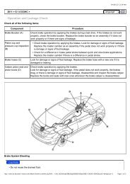
Check the ground circuit for the diagnosis<br />
1. Check for continuity between terminal 4 of the data link connector <strong>and</strong> body ground.<br />
2. Is there continuity?<br />
▶ Repair an open in the wire between terminal 4 of the data link connector <strong>and</strong> ground point.<br />
Communication with GDS is not possible.<br />
(Communication with ABS only is not possible.)<br />
Detecting condition<br />
Trouble Symptoms<br />
When communication with GDS is not possible, the cause may be probably an open in<br />
the HECU power circuit or an open in the diagnosis output circuit.<br />
Possible Cause<br />
- An open in the wire<br />
- Faulty HECU<br />
- Faulty power source circuit<br />
Inspection procedures<br />
Check for Continuity in the CAN Line<br />
1. Disconnect the connector from the ABS control module.<br />
2. Check for continuity between terminals 26, 14 of the ABS control module connector <strong>and</strong> 3, 11 of the data link connector.<br />
3. Is there continuity?<br />
▶ Check the power source of ABS control module.<br />
▶ Repair an open in the wire.<br />
Check the power source of ABS control module<br />
1. Disconnect the connector from the ABS control module.<br />
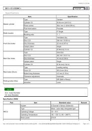
2. Turn the ignition switch ON, measure the voltage between terminal 29 of the ABS control module harness side connector <strong>and</strong> body ground.<br />
Specification : approximately B+<br />
3. Is voltage within specification?<br />
▶ Check for poor ground.<br />
http://service.hyundai-motor.com/Main/Viewer/content.asp?IsP…2011%26nbsp%3B%26gt%3B%26nbsp%3BG+1%2E6+DOHC&cat2=&imgnum=1<br />
Page 6 of 14


![mahindra parts catalog[1].pdf - The Automotive India](https://img.yumpu.com/46820768/1/190x245/mahindra-parts-catalog1pdf-the-automotive-india.jpg?quality=85)