Effect of Pressure Angle on Transmission Efficiency of Helical Gears
Effect of Pressure Angle on Transmission Efficiency of Helical Gears
Effect of Pressure Angle on Transmission Efficiency of Helical Gears

You also want an ePaper? Increase the reach of your titles
YUMPU automatically turns print PDFs into web optimized ePapers that Google loves.
<str<strong>on</strong>g>Effect</str<strong>on</strong>g> <str<strong>on</strong>g>of</str<strong>on</strong>g> <str<strong>on</strong>g>Pressure</str<strong>on</strong>g> <str<strong>on</strong>g>Angle</str<strong>on</strong>g> <strong>on</strong> Transmissi<strong>on</strong> <strong>Efficiency</strong> <str<strong>on</strong>g>of</str<strong>on</strong>g> <strong>Helical</strong> <strong>Gears</strong><br />
Rolling fricti<strong>on</strong> loss:- The rolling fricti<strong>on</strong> loss is<br />
dependent <strong>on</strong> the instantaneous rolling velocity and the<br />
instantaneous lubricant film thickness. As the gear teeth come<br />
into mesh, an elastohydrodynamic lubricant film is developed<br />
between the teeth in c<strong>on</strong>tact. The acti<strong>on</strong> <str<strong>on</strong>g>of</str<strong>on</strong>g> the gear teeth<br />
during the engagement draws the lubricant into the c<strong>on</strong>tact<br />
z<strong>on</strong>e. The parameters that influence the rolling fricti<strong>on</strong> loss<br />
are the lubricant film thickness, the angular velocity <str<strong>on</strong>g>of</str<strong>on</strong>g> the<br />
gears, the working pressure angle and the point <str<strong>on</strong>g>of</str<strong>on</strong>g> c<strong>on</strong>tact<br />
al<strong>on</strong>g its c<strong>on</strong>tact path. The lubricant properties influence the<br />
buildup <str<strong>on</strong>g>of</str<strong>on</strong>g> the lubricant film, its shear values and its thermal<br />
behavior. In additi<strong>on</strong>, the gear material and the normal tooth<br />
load also influence the film thickness.<br />
Spin power losses <str<strong>on</strong>g>of</str<strong>on</strong>g> a gearbox are either due to churning <str<strong>on</strong>g>of</str<strong>on</strong>g><br />
the lubricant if the rotating comp<strong>on</strong>ents <str<strong>on</strong>g>of</str<strong>on</strong>g> the gearbox are<br />
immersed in an oil bath (dip-lubricated) or due to windage if<br />
the lubricati<strong>on</strong> method is jet-type and the surrounding<br />
medium is air or a fine mist <str<strong>on</strong>g>of</str<strong>on</strong>g> air and oil. Focusing <strong>on</strong> the<br />
most fundamental comp<strong>on</strong>ent <str<strong>on</strong>g>of</str<strong>on</strong>g> the gearbox, i.e. a gear pair<br />
in mesh, this chapter aims at developing a novel<br />
physics-based fluid mechanics model <str<strong>on</strong>g>of</str<strong>on</strong>g> oil churning losses<br />
due to interacti<strong>on</strong>s <str<strong>on</strong>g>of</str<strong>on</strong>g> the gears, both as a pair and as<br />
individual entities, with the surrounding lubricant medium.<br />
III. LITERATURE REVIEW<br />
Robert F. Handschuh et al completed a preliminary study<br />
to determine the feasibility <str<strong>on</strong>g>of</str<strong>on</strong>g> using high-pressure angle gears<br />
in aer<strong>on</strong>autic and space applicati<strong>on</strong>s[1]. Y. Michlin et al<br />
described a methodology for analysis <str<strong>on</strong>g>of</str<strong>on</strong>g> gear transmissi<strong>on</strong><br />
with allowances for the power losses due to both the rolling<br />
and sliding fricti<strong>on</strong>. The latter fricti<strong>on</strong>, incorporated in the<br />
traditi<strong>on</strong>al methods, does not by itself account for the wear <str<strong>on</strong>g>of</str<strong>on</strong>g><br />
the teeth at c<strong>on</strong>tact sites adjoining the pitch point, where the<br />
rolling losses are paramount[2]. Xu Hai et al proposed a<br />
computati<strong>on</strong>al model for the predicti<strong>on</strong> <str<strong>on</strong>g>of</str<strong>on</strong>g> fricti<strong>on</strong>-related<br />
mechanical efficiency losses <str<strong>on</strong>g>of</str<strong>on</strong>g> parallel-axis gear pairs. The<br />
model incorporates a gear load distributi<strong>on</strong> model, a fricti<strong>on</strong><br />
model, and a mechanical efficiency formulati<strong>on</strong> to predict the<br />
instantaneous mechanical efficiency <str<strong>on</strong>g>of</str<strong>on</strong>g> a gear pair under<br />
typical operating, surface, and lubricati<strong>on</strong> c<strong>on</strong>diti<strong>on</strong>s[3].<br />
Sheng Li et al studied the influence <str<strong>on</strong>g>of</str<strong>on</strong>g> basic design<br />
parameters and tooth surface modificati<strong>on</strong>s <strong>on</strong> the mechanical<br />
(fricti<strong>on</strong> induced) power losses <str<strong>on</strong>g>of</str<strong>on</strong>g> a helical gear pair[4]. S.<br />
Seetharaman et al proposed a physics-based fluid mechanics<br />
model to predict spin power losses <str<strong>on</strong>g>of</str<strong>on</strong>g> gear pairs due to oil<br />
churning and windage[5]. Shanming Luo et al developed a<br />
geometric relati<strong>on</strong>ship and mathematical model <str<strong>on</strong>g>of</str<strong>on</strong>g> pressure<br />
angle <str<strong>on</strong>g>of</str<strong>on</strong>g> elliptical gears based <strong>on</strong> the theory <str<strong>on</strong>g>of</str<strong>on</strong>g> gearing, and<br />
some c<strong>on</strong>straints <str<strong>on</strong>g>of</str<strong>on</strong>g> pressure angle are presented in order to<br />
prevent gear teeth from coming out <str<strong>on</strong>g>of</str<strong>on</strong>g> mesh[6]. C. Changenet<br />
et al presented a series <str<strong>on</strong>g>of</str<strong>on</strong>g> formulas which enable accurate<br />
predicti<strong>on</strong>s <str<strong>on</strong>g>of</str<strong>on</strong>g> churning losses for <strong>on</strong>e pini<strong>on</strong> characteristic <str<strong>on</strong>g>of</str<strong>on</strong>g><br />
automotive transmissi<strong>on</strong> geometry. The results are based <strong>on</strong><br />
dimensi<strong>on</strong>al analysis and have been experimentally validated<br />
over a wide range <str<strong>on</strong>g>of</str<strong>on</strong>g> speeds, gear geometries, lubricants, and<br />
immersi<strong>on</strong> depths[7]. Petra Heingartner et al reviewed some<br />
<str<strong>on</strong>g>of</str<strong>on</strong>g> the mathematical models proposed for the individual<br />
comp<strong>on</strong>ents associated with speed and load dependant losses,<br />
such as windage, churning, sliding and rolling fricti<strong>on</strong><br />
losses[8]. T. T. Petry-Johns<strong>on</strong> et al developed a test<br />
methodology for the measurement <str<strong>on</strong>g>of</str<strong>on</strong>g> spur gear efficiency<br />
under high-speed and variable torque c<strong>on</strong>diti<strong>on</strong>s. A<br />
power-circulating test machine was designed to operate at<br />
speeds to 10,000 rpm and transmitted power levels to 700<br />
kW[9].<br />
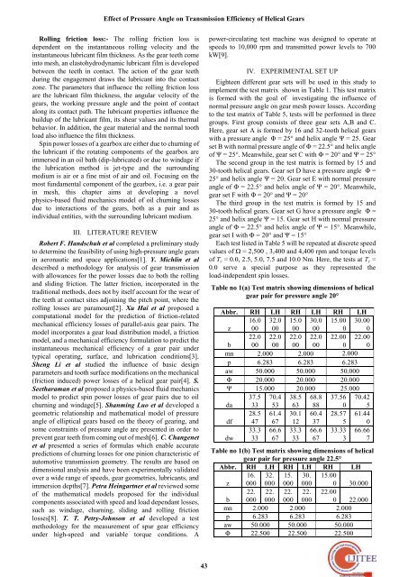
IV. EXPERIMENTAL SET UP<br />
Eighteen different gear sets will be used in this study to<br />
implement the test matrix shown in Table 1. This test matrix<br />
is formed with the goal <str<strong>on</strong>g>of</str<strong>on</strong>g> investigating the influence <str<strong>on</strong>g>of</str<strong>on</strong>g><br />
normal pressure angle <strong>on</strong> gear mesh power losses. According<br />
to the test matrix <str<strong>on</strong>g>of</str<strong>on</strong>g> Table 5, tests will be performed in three<br />
groups. First group c<strong>on</strong>sists <str<strong>on</strong>g>of</str<strong>on</strong>g> three gear sets A,B and C.<br />
Here, gear set A is formed by 16 and 32-tooth helical gears<br />
with a pressure angle Φ = 25° and helix angle Ψ = 25. Gear<br />
set B with normal pressure angle <str<strong>on</strong>g>of</str<strong>on</strong>g> Φ = 22.5° and helix angle<br />
<str<strong>on</strong>g>of</str<strong>on</strong>g> Ψ = 25°. Meanwhile, gear set C with Φ = 20° and Ψ = 25°<br />
The sec<strong>on</strong>d group in the test matrix is formed by 15 and<br />
30-tooth helical gears. Gear set D have a pressure angle Φ =<br />
25° and helix angle Ψ = 20. Gear set E with normal pressure<br />
angle <str<strong>on</strong>g>of</str<strong>on</strong>g> Φ = 22.5° and helix angle <str<strong>on</strong>g>of</str<strong>on</strong>g> Ψ = 20°. Meanwhile,<br />
gear set F with Φ = 20° and Ψ = 20°<br />
The third group in the test matrix is formed by 15 and<br />
30-tooth helical gears. Gear set G have a pressure angle Φ =<br />
25° and helix angle Ψ = 15. Gear set H with normal pressure<br />
angle <str<strong>on</strong>g>of</str<strong>on</strong>g> Φ = 22.5° and helix angle <str<strong>on</strong>g>of</str<strong>on</strong>g> Ψ = 15°. Meanwhile,<br />
gear set I with Φ = 20° and Ψ = 15°<br />
Each test listed in Table 5 will be repeated at discrete speed<br />
values <str<strong>on</strong>g>of</str<strong>on</strong>g> Ω = 2,500 , 3,400 and 4,400 rpm and torque levels<br />
<str<strong>on</strong>g>of</str<strong>on</strong>g> T c = 0.0, 2.5, 5.0, 7.5 and 10.0 Nm. Here, the tests at T c =<br />
0.0 serve a special purpose as they represented the<br />
load-independent spin losses.<br />
Table no 1(a) Test matrix showing dimensi<strong>on</strong>s <str<strong>on</strong>g>of</str<strong>on</strong>g> helical<br />
gear pair for pressure angle 20°<br />
Abbr. RH LH RH LH RH LH<br />
z<br />
16.0<br />
00<br />
32.0<br />
00<br />
15.0<br />
00<br />
30.0<br />
00<br />
15.00<br />
0<br />
30.00<br />
0<br />
b<br />
22.0<br />
00<br />
22.0<br />
00<br />
22.0<br />
00<br />
22.0<br />
00<br />
22.00<br />
0<br />
22.00<br />
0<br />
mn 2.000 2.000 2.000<br />
p 6.283 6.283 6.283<br />
aw 50.000 50.000 50.000<br />
Φ 20.000 20.000 20.000<br />
Ψ 15.000 20.000 25.000<br />
da<br />
37.5<br />
33<br />
70.4<br />
53<br />
38.5<br />
63<br />
68.8<br />
88<br />
37.56<br />
0<br />
70.42<br />
5<br />
df<br />
28.5<br />
47<br />
61.4<br />
67<br />
30.1<br />
12<br />
60.4<br />
37<br />
28.57<br />
5<br />
61.44<br />
0<br />
dw<br />
33.3<br />
33<br />
66.6<br />
67<br />
33.3<br />
33<br />
66.6<br />
67<br />
33.33<br />
3<br />
66.66<br />
7<br />
Table no 1(b) Test matrix showing dimensi<strong>on</strong>s <str<strong>on</strong>g>of</str<strong>on</strong>g> helical<br />
gear pair for pressure angle 22.5°<br />
Abbr. RH LH RH LH RH LH<br />
16. 32. 15. 30. 15.00<br />
z 000 000 000 000<br />
22. 22. 22. 22.<br />
b 000 000 000 000<br />
mn 2.000 2.000 2.000<br />
p 6.283 6.283 6.283<br />
aw 50.000 50.000 50.000<br />
Φ 22.500 22.500 22.500<br />
0 30.000<br />
22.00<br />
0 22.000<br />
43