KD135GX-LFBSï½KD245GX-LFB - KYOCERA Solar
KD135GX-LFBSï½KD245GX-LFB - KYOCERA Solar
KD135GX-LFBSï½KD245GX-LFB - KYOCERA Solar

You also want an ePaper? Increase the reach of your titles
YUMPU automatically turns print PDFs into web optimized ePapers that Google loves.
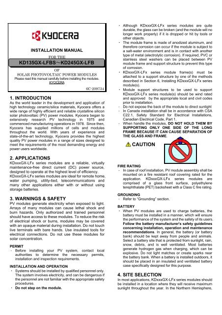
INSTALLATION MANUAL<br />
FOR THE<br />
<strong>KD135GX</strong>-<strong>LFB</strong>S~KD245GX-<strong>LFB</strong><br />
OF<br />
SOLAR PHOTOVOLTAIC POWER MODULES<br />
Please read this manual carefully before installing the modules.<br />
<strong>KYOCERA</strong><br />
6C-209734<br />
1. INTRODUCTION<br />
As the world leader in the development and application of<br />
high technology ceramic/silica materials, Kyocera offers a<br />
wide range of highly efficient and reliable crystalline silicon<br />
solar photovoltaic (PV) power modules. Kyocera began to<br />
extensively research PV technology in 1975 and<br />
commenced manufacturing operations in 1978. Since then,<br />
Kyocera has supplied millions of cells and modules<br />
throughout the world. With years of experience and<br />
state-of-the-art technology, Kyocera provides the highest<br />
quality PV power modules in a range of sizes designed to<br />
meet the requirements of the most demanding energy and<br />
power users worldwide.<br />
2. APPLICATIONS<br />
KDxxxGX-LFx series modules are a reliable, virtually<br />
maintenance-free direct current (DC) power source,<br />
designed to operate at the highest level of efficiency.<br />
KDxxxGX-LFx series modules are ideal for remote home,<br />
water pumping, utility-tied, telecommunications and<br />
many other applications either with or without using<br />
storage batteries.<br />
3. WARNINGS & SAFETY<br />
PV modules generate electricity when exposed to light.<br />
Arrays of many modules can cause lethal shock and<br />
burn hazards. Only authorized and trained personnel<br />
should have access to these modules. To reduce the risk<br />
of electrical shock or burns, modules may be covered<br />
with an opaque material during installation. Do not touch<br />
live terminals with bare hands. Use insulated tools for<br />
electrical connections. Do not use these modules for<br />
solar concentration.<br />
PERMIT<br />
・ Before installing your PV system, contact local<br />
authorities to determine the necessary permits,<br />
installation and inspection requirements.<br />
INSTALLATION AND OPERATION<br />
・ Systems should be installed by qualified personnel only.<br />
The system involves electricity, and can be dangerous if<br />
the personnel are not familiar with the appropriate safety<br />
procedures.<br />
・ Do not step on the module.<br />
・ Although KDxxxGX-LFx series modules are quite<br />
durable, the glass can be broken (and the module will no<br />
longer work properly) if it is dropped or hit by tools or<br />
other objects.<br />
・ The module frame is made of anodized aluminum, and<br />
therefore corrosion can occur if the module is subject to<br />
a salt-water environment and is in contact with another<br />
type of metal (electrolytic corrosion). If required, PVC or<br />
stainless steel washers can be placed between PV<br />
module frame and support structure to prevent this type<br />
of corrosion.<br />
・ KDxxxGX-LFx series module frame(s) must be<br />
attached to a support structure by one of the methods<br />
described in Section 6, Installing KDxxxGX-LFx series<br />
module(s).<br />
・ Module support structures to be used to support<br />
KDxxxGX-LFx series module(s) should be wind rated<br />
and approved by the appropriate local and civil codes<br />
prior to installation.<br />
・ Do not expose the back of the module to direct sunlight<br />
・ In Canada installation shall be in accordance with CSA<br />
C22.1, Safety Standard for Electrical Installations,<br />
Canadian Electrical Code, Part 1.<br />
・ When handle the modules, DO NOT HOLD THEM BY<br />
SUPPORTING ONLY ONE SIDE OF THE LONG<br />
FRAME BECAUSE IT CAN CAUSE SEPARATION OF<br />
THE GLASS AND FRAME.<br />
CAUTION<br />
FIRE RATING<br />
・ In case of roof installation, PV module assembly shall be<br />
mounted on a fire resistant roof covering rated for the<br />
application. KDxxxGX-LFx series modules are<br />
comprised of a glass front surface, polyethylene<br />
terephthalate (PET) backsheet with a Class C fire rating.<br />
GROUNDING<br />
・ Refer to “Grounding” section.<br />
BATTERY<br />
・ When PV modules are used to charge batteries, the<br />
battery must be installed in a manner, which will ensure<br />
the performance of the system and the safety of its users.<br />
Follow the battery manufacturer’s safety guidelines<br />
concerning installation, operation and maintenance<br />
recommendations. In general, the battery (or battery<br />
bank) should be kept away from people and animals.<br />
Select a battery site that is protected from sunlight, rain,<br />
snow, debris, and is well ventilated. Most batteries<br />
generate hydrogen gas when charging, which can be<br />
explosive. Do not light matches or create sparks near<br />
the battery bank. When a battery is installed outdoors, it<br />
should be placed in an insulated and ventilated battery<br />
case specifically designed for this purpose.<br />
4. SITE SELECTION<br />
In most applications, KDxxxGX-LFx series modules should<br />
be installed in a location where they will receive maximum<br />
sunlight throughout the year. In the Northern Hemisphere,
the modules should typically face south, and in the<br />
Southern Hemisphere, the modules should typically face<br />
north. Modules facing 30 degrees away from true South (or<br />
North) will lose approximately 10 to 15 percent of their<br />
power output. If the module faces 60 degrees away from<br />
true South (or North), the power loss will be 20 to 30 percent.<br />
When choosing a site, avoid trees, buildings or obstructions,<br />
which could cast shadows on PV modules especially during<br />
the winter season when the arc of the sun is lowest over the<br />
horizon.<br />
5. MODULE TILT ANGLE<br />
KDxxxGX-LFx series modules produce bigger power when<br />
they are pointed directly at the sun.<br />
For grid tie installations where the PV modules are attached<br />
to a permanent structure, PV modules should be tilted at an<br />
angle equal to the site's latitude. This will typically result in<br />
the highest annual energy output.<br />
6. INSTALLING KDxxxGX-LFx SERIES<br />
MODULES<br />
To install the module, use bolt and nut on installation holes<br />
which are opened in the module frame and install the<br />
module by following the instruction below.<br />
The minimum spacing of 2” (50 mm) is required between PV<br />
module and the mounting surface around the perimeter of<br />
PV module. KDxxxGX-LFx series modules may be<br />
installed in various applications utilizing a variety of support<br />
structure options and attachment methods. For optimal<br />
performance in all applications, clearance between the<br />
module frame and the mounting surface is required to allow<br />
cooler ambient air to circulate around the back of the<br />
module and to avoid the module and / or wiring damage. A<br />
minimum of .13” (3.2 mm) spacing must also be maintained<br />
between module frames to allow for thermal expansion.<br />
KDxxxGX-LFx series modules may be attached to a<br />
support structure by the following methods. When installing<br />
modules in snowy area, an appropriate countermeasure<br />
has to be taken to prevent possible damages to the lower<br />
side frame by slipping snow (e.g. attach supporting parts to<br />
the lowest modules.). Any damage caused by snow or such<br />
countermeasure is not covered under warranty.<br />
BOLTING: Utilizing 5/16” or 8 mm steel hardware structure<br />
through the existing .35” (9 mm) diameter mounting holes in<br />
the module frame and then through KDxxxGX-LFx series<br />
module mounting holes on the support structure. Tighten<br />
the screws with adequate torque (usually 132 in-lb).<br />
Support structure should have enough strength to keep the<br />
mounting span. Refer to the Module Drawings for the<br />
position of PV module mounting holes.<br />
7. MODULE WIRING<br />
KDxxxGX-LFx series modules come pre-wired with<br />
terminals ready for most building attachments or free<br />
standing installations. Each module has two #12 AWG type<br />
PV-wire stranded sunlight resistant output cables each<br />
terminated with Multi-Contact locking connectors. The<br />
positive (+) terminal has a male connector while the<br />
negative (-) terminal has a female connector. The module<br />
wiring is solely for series connections only, i.e. male (+) to<br />
female (-) interconnections. Series and parallel connections<br />
shall be made by use of two #10-14 AWG type PV-wire<br />
stranded sunlight resistant and insulated for 90℃ minimum<br />
output cables with male and female Multi-Contact locking<br />
connectors.<br />
NOTE: When making connections with Multi-Contact<br />
connectors, make sure the array is disabled. DO NOT<br />
MAKE CONNECTIONS WHILE UNDER LOAD. Module<br />
output connections are marked “Do not disconnect under<br />
load”.<br />
NOTE: MAXIMUM SYSTEM VOLTAGE 600 VDC.<br />
KDxxxGX-LFx series modules and most PV system<br />
components have a maximum system voltage rating of 600<br />
volts DC. Some grid feed in systems operate at or near this<br />
voltage rating. Like other polycrystalline the PV modules,<br />
the open circuit voltage of the KDxxxGX-LFx series<br />
modules increases as the ambient temperature decreases.<br />
Maximum system voltage is computed as the sum of the<br />
open-circuit voltage of the series-connected PV modules for<br />
the lowest expected ambient temperature. Refer to the<br />
National Electrical Code Article 690-7(a) for determining the<br />
maximum number of KDxxxGX-LFx series modules that<br />
can be placed in series. Temperature coefficients, specific<br />
to the module of use, can be used to provide the most<br />
accurate prediction of module voltage under temperature<br />
extremes.<br />
NOTE: Install the maximum number of series connection for<br />
the KDxxxGX-LFx series modules so that the system<br />
voltage is less than 600 V.<br />
NOTE: Do not connect the modules in parallel without<br />
maximum over current protection.<br />
NOTE: The minimum diameter that the cable can be bent<br />
for the KDxxxGX-LFx series modules is 1.93” (49mm).<br />
NOTE: In normal conditions, PV modules may produce<br />
larger current and / or voltage than reported in the standard<br />
test conditions. Therefore, when voltage evaluations for<br />
components, capacity of conductors, size of fuses, and size<br />
of control systems connected to the module output are<br />
determined, multiply the values of short- circuit current (Isc)<br />
and open-circuit voltage (Voc) that are marked in<br />
KDxxxGX-LFx series modules by the coefficient, 1.25.<br />
NOTE: Refer to Section 690-8 of the National Electrical<br />
Code for an additional multiplying factor of 125 percent (80<br />
percent derating) which may be applicable.<br />
8. GROUNDING<br />
Before installation, contact the local code authorities to<br />
determine the necessary grounding requirements. When<br />
installing in US market, attach all PV module frames to an<br />
earth ground in accordance with the National Electrical<br />
Code (NEC) Article 250. Proper grounding is achieved by<br />
connecting PV module frames and all metallic structural<br />
members contiguously to one another using a suitable<br />
grounding conductor. The grounding conductor shall be of<br />
copper, copper alloy or another material suitable for use as<br />
an electrical conductor per NEC. The grounding conductor<br />
must then make a connection to earth using a suitable earth<br />
grounding electrode. Ensure positive electrical contact<br />
through the anodizing on the module frame extrusion by<br />
utilizing one of the following methods. Attach the grounding<br />
conductor:
(1)to one of the .35” (9mm) diameter holes marked “ground”<br />
using 5/16” stainless steel hardware. Wrap conductor<br />
around bolt. Tighten the screws with adequate torque<br />
(usually 132 in-lb). Avoid direct contact of copper ground<br />
conductor to aluminum frame.<br />
(2)to a ground lug (manufacturer:ILSCO,model:GBL-4DBT).<br />
Tighten the screws with adequate torque (usually 62<br />
in-lb). Use #10-32 stainless steel hardware to attach the<br />
lug to the module frame by the torque of 40 in-lb. A<br />
stainless steel star washer, positioned between the lug<br />
and the anodized surface of the frame, must be employed<br />
to break through the anodized layer of the frame<br />
extrusion and electrically connect the ground lug to the<br />
conducting aluminum frame material.<br />
As a general rule, avoid direct contact of copper or copper<br />
alloy ground conductors with the aluminum module frame.<br />
All ground bond securing hardware in contact with either the<br />
aluminum module frame and / or copper or copper alloy<br />
ground conductors must be stainless steel.<br />
Nut<br />
Spring washer<br />
Flat washer<br />
Ground conductor<br />
Cup washer<br />
Star washer<br />
Aluminum frame<br />
Flat washer<br />
Bolt<br />
Nut<br />
Spring washer<br />
Ground lug<br />
Star washer<br />
Aluminum<br />
frame<br />
Flat washer<br />
Bolt<br />
9. BLOCKING DIODES<br />
In systems utilizing a battery, blocking diodes are typically<br />
placed between the battery and PV module output to<br />
prevent battery from discharging at night. KDxxxGX-LFx<br />
series modules are made of polycrystalline cells with high<br />
electrical “back flow” resistance to nighttime battery<br />
discharging. As a result, KDxxxGX-LFx series modules do<br />
not contain a blocking diode when shipped from the factory.<br />
Most PV charge regulators and inverters incorporate<br />
nighttime disconnect feature.<br />
maximum system voltage at lowest PV module<br />
operating temperature.<br />
11. MAINTENANCE<br />
KDxxxGX-LFx series modules are designed for long life<br />
and require very little maintenance. Under most weather<br />
conditions, normal rainfall is sufficient to keep the module<br />
glass surface clean. If dirt build-up becomes excessive,<br />
clean the glass surface only with a soft cloth using mild<br />
detergent and water. USE CAUTION WHEN CLEANING<br />
THE BACK SURFACE OF PV MODULE TO AVOID<br />
PENETRATING BACK SHEET. PV modules that are<br />
mounted flat (0°tilt angle) should be cleaned more often,<br />
as they will not "self clean" as effectively as modules<br />
mounted at a 15°tilt or greater. Once a year, check the<br />
general condition of the wiring and check to be sure that<br />
mounting hardware is tight. Loose connections may result<br />
in a damaged module or array.<br />
<strong>KYOCERA</strong> <strong>Solar</strong> Group Sales Office<br />
• <strong>KYOCERA</strong> Corporation<br />
Corporate <strong>Solar</strong> Energy Group<br />
6 Takeda Tobadono-cho Fushimi-ku, Kyoto 612-8501, Japan<br />
Phone: 81-75-604-3476<br />
Fax: 81-75-604-3475<br />
http://www.kyocera.com/<br />
• <strong>KYOCERA</strong> <strong>Solar</strong>, Inc.<br />
7812 East Acoma Drive, Scottsdale, AZ 85260, U.S.A.<br />
Phone: 1-480-948-8003 or 1-800-223-9580<br />
Fax: 1-480-483-6431<br />
http://www.kyocerasolar.com/<br />
• <strong>KYOCERA</strong> <strong>Solar</strong> Pty Ltd.<br />
Level 3, 6-10 Talavera Road, North Ryde NSW 2113, Australia<br />
Phone: 61-2-9870-3946<br />
Fax: 61-2-9888-9673<br />
http://www.kyocerasolar.com.au/<br />
• <strong>KYOCERA</strong> <strong>Solar</strong> do Brasil Ltda.<br />
Av. das Americas, 20007 – Bloco 2 – Salas (rooms) 105 to 108,<br />
Rio de Janeiro, 22790-851, Brazil<br />
Phone: 55-21-3724-3900<br />
Fax: 55-21-3724-3911<br />
http://www.kyocerasolar.com.br/<br />
10. BYPASS DIODES<br />
Partial shading of an individual module in a source circuit<br />
string (i.e. two or more modules connected in series) can<br />
cause a reverse voltage across the shaded cells within the<br />
module. Module output current is then forced through the<br />
shaded area by the remaining illuminated cells and other<br />
PV modules in series with the partially shaded module(s).<br />
The current forced through the shaded cells within PV<br />
module (or modules) causes additional module heating and<br />
severe loss of power. All KDxxxGX-LFx series modules are<br />
supplied with factory installed (non user serviceable)<br />
bypass diodes.<br />
The purpose of bypass diodes is to provide a low-resistance<br />
current path around the shaded cells, thereby minimizing<br />
PV module heating and array current losses.<br />
PV modules employ bypass diodes that have:<br />
・ Rated Average Forward Current [I F(AV) ] Above<br />
maximum system current at highest PV module<br />
operating temperature.<br />
・ Rated Repetitive Peak Reverse Voltage [V RRM ] Above
12. SPECIFICATIONS<br />
・ Under certain conditions, a photovoltaic module may produce more voltage and current than reported at Standard Test<br />
Conditions (STC). Refer to Section 690 of the National Electrical Code for guidance in series string sizing and choosing<br />
overcurrent protection.<br />
Kyocera KDxxxGX-LFx Series Module Specification<br />
Electrical Characteristics: @ STC<br />
Module Type <strong>KD135GX</strong>-<strong>LFB</strong>S KD140GX-<strong>LFB</strong>S KD215GX-<strong>LFB</strong>S KD220GX-<strong>LFB</strong>S KD235GX-<strong>LFB</strong> KD240GX-<strong>LFB</strong> KD245GX-<strong>LFB</strong><br />
Pmax 135 140 215 220 235 240 245<br />
Voc 22.1 22.1 33.2 33.2 36.9 36.9 36.9<br />
Isc 8.37 8.68 8.78 8.98 8.55 8.59 8.91<br />
Vpm 17.7 17.7 26.6 26.6 29.8 29.8 29.8<br />
Ipm 7.63 7.91 8.09 8.28 7.89 8.06 8.23<br />
Factory installed Bypass Diode<br />
(QTY) 2 3<br />
Series Fuse Rating 15<br />
Thermal Characteristics: Temp. Coefficient<br />
Voc (V/°C) -0.80×10 -1 -0.80×10 -1 -1.20×10 -1 -1.20×10 -1 -1.33×10 -1 -1.33×10 -1 -1.33×10 -1<br />
I sc (A/°C) 5.02×10 -3 5.21×10 -3 5.27×10 -3 5.39×10 -3 5.13×10 -3 5.15×10 -3 5.35×10 -3<br />
Vpm (V/℃) -0.92×10 -1 -0.92×10 -1 -1.39×10 -1 -1.39×10 -1 -1.54×10 -1 -1.54×10 -1 -1.55×10 -1<br />
Physical Characteristics:<br />
Length 59.06” (1500mm) 59.06” (1500mm) 59.06” (1500mm) 59.06” (1500mm) 65.43” (1662mm) 65.43” (1662mm) 65.43” (1662mm)<br />
Width 26.30” (668mm) 26.30” (668mm) 38.98” (990mm) 38.98” (990mm) 38.98” (990mm) 38.98” (990mm) 38.98” (990mm)<br />
Depth 1.81” (46mm) 1.81” (46mm) 1.81” (46mm) 1.81” (46mm) 1.81” (46mm) 1.81” (46mm) 1.81” (46mm)<br />
Weight 28.4 lb (12.9 kg) 28.4 lb (12.9 kg) 41.0 lb(18.6 kg) 41.0 lb(18.6 kg) 46.3 lb(21.0 kg) 46.3 lb(21.0 kg) 46.3 lb(21.0 kg)<br />
Mounting Hole<br />
Diameter 9mm Quantity 4pcs<br />
Grounding Hole<br />
Diameter 9mm Quantity 4pcs<br />
Application Class<br />
Class A<br />
NOTES<br />
(1) The electrical characteristics are within +/-5% of the installed values of Pmax and within +/-10% of the installed values of Isc and Voc<br />
under standard test conditions (irradiance of 1000W/m 2 , AM 1.5 spectrum, and a cell temperature of 25 deg C).<br />
(2) See module specification sheet for most recent electrical characteristics.<br />
(3) See module drawing for mounting grounding holes locations.<br />
MODULE DIMENSIONS<br />
MODULE DIMENSIONS<br />
MODULE TYPE<br />
DIM.A<br />
DIM.B<br />
DIM.C<br />
DIM.D<br />
DIM.E<br />
DIM.F<br />
DIM.G<br />
MODULE TYPE<br />
DIM.A<br />
DIM.B<br />
DIM.C<br />
DIM.D<br />
DIM.E<br />
DIM.F<br />
DIM.G<br />
<strong>KD135GX</strong>-<strong>LFB</strong>S,KD140GX-<strong>LFB</strong>S<br />
59.06"<br />
26.30"<br />
25.31"<br />
.49"<br />
10.96"<br />
37.13"<br />
.35"<br />
KD235GX-<strong>LFB</strong>,KD240GX-<strong>LFB</strong>,KD245GX-<strong>LFB</strong><br />
65.43"<br />
38.98"<br />
37.99"<br />
.49"<br />
11.06"<br />
43.31"<br />
.35"<br />
KD215GX-<strong>LFB</strong>S,KD220GX-<strong>LFB</strong>S<br />
59.06"<br />
38.98"<br />
37.99"<br />
.49"<br />
10.96"<br />
37.13"<br />
.35"<br />
“A”<br />
"E"<br />
"F"<br />
<strong>KD135GX</strong>-<strong>LFB</strong>S<br />
KD140GX-<strong>LFB</strong>S<br />
33.1"<br />
39.8"<br />
WIRE<br />
WIRE<br />
LENGTH<br />
LENGTH<br />
φ“G”<br />
[TYP.]<br />
“A”<br />
"F" "E"<br />
KD215GX-<strong>LFB</strong>S<br />
KD220GX-<strong>LFB</strong>S<br />
35.4"<br />
WIRE<br />
LENGTH<br />
43.3"<br />
WIRE<br />
LENGTH<br />
φ“G”<br />
[TYP.]<br />
"A"<br />
a<br />
a<br />
b<br />
"D"<br />
“C” b<br />
“B”<br />
GROUND HOLE<br />
MARKED<br />
GROUND HOLE<br />
MARKED<br />
0.41"<br />
1.81"<br />
1.81"<br />
"E"<br />
"F"<br />
KD235GX-<strong>LFB</strong><br />
KD240GX-<strong>LFB</strong><br />
KD245GX-<strong>LFB</strong><br />
37.8"<br />
WIRE<br />
LENGTH<br />
46.9"<br />
WIRE<br />
LENGTH<br />
a<br />
a<br />
a<br />
a<br />
b<br />
"D"<br />
“C”<br />
“B”<br />
b<br />
"D"<br />
"C"<br />
"B"<br />
b<br />
b<br />
0.47"<br />
0.79"<br />
SECTION a-a<br />
1.18"<br />
0.47"<br />
SECTION b-b