bba hapas - Durey Castings
bba hapas - Durey Castings
bba hapas - Durey Castings

Create successful ePaper yourself
Turn your PDF publications into a flip-book with our unique Google optimized e-Paper software.
6.4 Should other materials be used in conjunction with the system (for example to repair/rebuild the supporting<br />
structure) such materials should have a strength commensurate with the reinstatement system.<br />
6.5 The frame and cover should be aligned so as to ensure safe access to the reinstatement.<br />
7 Preparation<br />
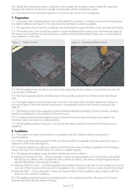
7.1 A perimeter area, indicating the minimum width needed for excavation, is marked out around the existing frame<br />
of a failed installation (see Figure 1). This area should be extended to include any defects.<br />
7.2 The supporting structure must be of adequate size and strength to support the frame, cover and expected loading.<br />
7.3 The marked area is saw cut and excavated to uncover the flange of the existing cover and frame (see Figure 2).<br />
The existing cover and frame are removed using a suitable mechanical lifting device, taking care to avoid dropping<br />
loose materials in to the shaft.<br />
Figure 1 Failed ironwork Figure 2 Excavating failed ironwork<br />
7.4 All old bedding mortar should be removed and the supporting structure cut back or loose bricks removed until<br />
a sound base is achieved.<br />
7.5 The newly exposed substrate should be clean and structurally sound prior to commencing the reinstatement<br />
work.<br />
7.6 The depth needed to install the frame and cover level to the road surface should be determined, taking into<br />
account the depth of the frame and the manufacturer’s recommended maximum and minimum thicknesses (see<br />
Table 3).<br />
7.7 The finishing course of the supporting structure should be adjusted accordingly. For brick structures, levelling<br />
should be achieved prior to the installation of the final course.<br />
7.8 Concrete structures should be repaired using conventional concrete repair techniques and materials. The<br />
Certificate holder can advise on suitable materials.<br />
7.9 All old bedding material, loose paint, rust and any other debris should be removed from the frame prior to<br />
installation.<br />
8 Installation<br />
8.1 The products are mixed and laid strictly in accordance with this Certificate and the manufacturer’s<br />
recommendations.<br />
8.2 When using Ultracrete Envirobed HA104 and Ultracrete M60, the substrate should be wetted down prior to<br />
application of the mortar (see Figure 3).<br />
8.3 If packing materials are used as to support and level the frame, they should be compatible with the bedding<br />
mortar to be used. The Certificate holder can advise on suitable materials.<br />
8.4 The appropriate bedding mortar should be mechanically mixed as follows:<br />
• Ultracrete Envirobed HA104 — 20 kg of powder is mixed with approximately one 2.5 litre bottle of Envirobed<br />
HA104 liquid to obtain a stiff, non-slump mix with a uniform consistency. The amount of liquid required may be<br />
adjusted depending on the required consistency<br />
• Ultracrete PY4 SG or WG — the filler should be slowly added to the resin in the ratio of one complete tin of resin to<br />
one pack of filler/activator and mixed until a homogeneous mix is obtained. Part tins or packs should not be mixed<br />
• Ultracrete M60 — 25 kg of powder is mixed with approximately 3 litres of potable water to obtain a stiff, nonslump<br />
mix with a uniform consistency.<br />
8.5 The bedding materials should be immediately placed on the supporting structure, allowing a 5 mm excess<br />
thickness and used within ten minutes of mixing.<br />
Page 4 of 8