Installation Instruction - Firestone
Installation Instruction - Firestone
Installation Instruction - Firestone

You also want an ePaper? Increase the reach of your titles
YUMPU automatically turns print PDFs into web optimized ePapers that Google loves.
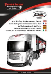
FRAME RAIL<br />
AIR<br />
SPRINGS<br />
AXLE STRAP<br />
AIR LINE<br />
PUSH-TO-CONNECT<br />
INFLATION VALVE<br />
DRIVER'S SIDE<br />
Figure "C"<br />
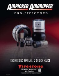
Figure "D"<br />
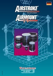
UPPER<br />
BRACKET<br />
AIR SPRING<br />
LOWER BRACKET<br />
BRAKE<br />
LINE<br />
FROM REAR, LOOKING TO FRONT<br />
4X4 & Z71/OFF ROAD<br />
BODY OF<br />
VEHICLE<br />
BUMPER<br />
AIR HOSE<br />
FLAT WASHER<br />
HEX NUT<br />
VALVE CAP<br />
Figure "B"<br />
INFLATION<br />
VALVES<br />
FRAME RAIL<br />
DRIVER'S SIDE<br />
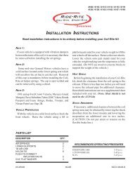
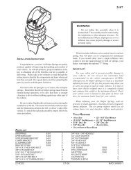
NOTE:<br />
Please read thorough<br />
this manual completely<br />
before installing the air<br />
spring kit to your vehicle.<br />
All illustrations reference<br />
the driver’s or left side of<br />
the vehicle. Reverse all<br />
orientations for the<br />
passenger’s or right side.<br />
STEP 1 - PREPARE<br />
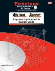
FROM REAR, LOOKING TO FRONT<br />
THE VEHICLE<br />
2WD, NON-Z71<br />
Remove the jounce<br />
bumper located under the<br />
frame rail or on the jounce bumper support. The jounce bumpers and<br />
bolts will not be reused with this kit.<br />
STEP 2 - PRE-ASSEMBLE THE KIT<br />
Select one air helper spring from your kit. Attach the lower<br />
bracket to the air spring using the 3/8"-16 x 5/8 flat head bolt. See<br />
Figure "A". Attach the upper bracket to the air spring with a 5/8"<br />
nylock nut. See Figure "A". The combination stud will use the<br />
larger diameter hole and the alignment "button" will use the smaller<br />
diameter hole. Install the elbow fitting into the air spring. Tighten the<br />
air fitting securely to engage the orange thread sealant. Position the<br />
fitting to point to the anticipated location of the air inflation valves,<br />
see Figure "A" & "C".<br />
STEP 3 - INSTALLING THE ASSEMBLY TO THE VEHICLE<br />
Place the assembly on the jounce stop of the driver’s side, see<br />
Figures "A" & "B".Using the existing jounce bumper holes, install<br />
the upper bracket onto the frame with 10MM x 30MM flat head<br />
bolts, see Figure "A". Attach the lower bracket to the axle using<br />
the axle strap or straps, 3/8"-16 x 2 1/2" carriage bolts, and 3/8"-16<br />
flange lock nuts, see Figure “A” & "B". Once the assembly is in<br />
place, you must have a minimum of 1/2" clearance around<br />
the air spring.<br />
STEP 4 - PASSENGER'S SIDE INSTALLATION<br />
Follow steps 1-3 with reverse orientations for assembly and installation of the passenger’s side.<br />
STEP 5 - INSTALL THE AIR LINE AND INFLATION VALVE<br />
Uncoil the airline tubing and cut it into two equal lengths. DO NOT FOLD OR KINK THE AIRLINE TUBING.<br />
Try to make the cut as square as possible. Insert one end of the airline tubing into the air fitting installed in the<br />
top of the air helper spring. Push the airline tubing into the fitting as far as possible see Figure “A”. Select a<br />
location on the vehicle for the air inflation valves. The location can be on the bumper or the body of the vehicle,<br />
as long as it is in a protected location so the valve will not be damaged, but maintain accessibility for the air<br />
chuck, see Figure “C”. Drill a 5/16" hole and install the air inflation valve using two 5/16" flat washers per<br />
valve as supports, see Figure “D”.<br />
Run the airline tubing from the air helper spring to the valve, routing it to avoid direct heat from the engine,<br />
exhaust pipe, and away from sharp edges. Thermal sleeves have been provided for these conditions.<br />
BRAKE<br />
LINE<br />
JOUNCE<br />
BUMPER<br />
SUPPORT<br />
AXLE STRAP<br />
UPPER<br />
BRACKET<br />
AIR SPRING<br />
LOWER BRACKET