Performance Evaluation of a Solar Wind-Ventilated Cabinet Dryer
Performance Evaluation of a Solar Wind-Ventilated Cabinet Dryer
Performance Evaluation of a Solar Wind-Ventilated Cabinet Dryer
Create successful ePaper yourself
Turn your PDF publications into a flip-book with our unique Google optimized e-Paper software.
B.O. Bolaji et al.: <strong>Performance</strong> <strong>Evaluation</strong> <strong>of</strong> a <strong>Solar</strong> <strong>Wind</strong>-<strong>Ventilated</strong> <strong>Cabinet</strong> <strong>Dryer</strong> 14<br />
cabinet dryer.<br />
2. Materials and Methods<br />
2.1 Theoretical Considerations<br />
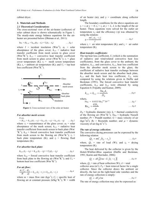
The cross-sectional view <strong>of</strong> the air-heater (collector) <strong>of</strong><br />
solar cabinet dryer is shown schematically in Figure 1.<br />
The steady-state energy balance equations for the airheater<br />
are presented below (Dhiman et al., 2011):<br />
Iα 1 + (h r 21 + h c21)(t 2 – t 1) = U t(t 1 – t a) …..Eq.1<br />
where I = incident insolation (Wm -2 ); α1 = solar<br />
absorptance <strong>of</strong> the glass cover; hr21 = radiative heat<br />
transfer coefficient from mesh screen to glass cover<br />
(Wm -2 K -1 ); hc21 = convective heat transfer coefficient<br />
from mesh screen to glass cover (Wm -2 K -1 ); t1 = glass<br />
cover temperature (K); t2 = mesh screen temperature<br />
(K); ta = ambient air temperature (K); and Ut = top heat<br />
loss coefficient (Wm -2 K -1 ).<br />
ti<br />
t1<br />
t2<br />
t3<br />
hr21<br />
hc3f<br />
y<br />
Ut<br />
Figure 1. Cross-sectional view <strong>of</strong> the solar air-heater<br />
For absorber mesh screen:<br />
Iτ 1α 2<br />
= (hr21 + h c21)(t 2 – t 1) + h r23 (t 2 – t 3) + h c2f (t 2 – t f) …..Eq.2<br />
where τ1 = transmittance <strong>of</strong> the glass cover; α2 = solar<br />
absorptance <strong>of</strong> the mesh screen; hr23 = radiative heat<br />
transfer coefficient from mesh screen to back plate (Wm -<br />
2 K -1 ); hr2f = forced convective heat transfer coefficient<br />
from mesh screen to the flowing air (Wm -2 K -1 ); t3 =<br />
back plate temperature (K); and tf = flowing fluid<br />
temperature (K).<br />
For absorber back plate:<br />
hc2f hr23<br />
Ub<br />
hc21<br />
hr23 (t2 – t3) = hc3f (t3 – tf) + Ub(t3 – ta) ……Eq.3<br />
where hr3f = forced convective heat transfer coefficient<br />
from back plate to the flowing air (Wm -2 K -1 ); and Ub =<br />
bottom heat loss coefficient (Wm -2 K -1 ).<br />
For air flow:<br />
m ⋅ C f dt f<br />
. = hc2<br />
f ( t2<br />
− t f ) + hc3<br />
f ( t3<br />
− t f ) ……Eq.4<br />
W dy<br />
where m = mass flow rate (kgs -1 ); Cf = specific heat <strong>of</strong><br />
flowing air at constant pressure (kJkg -1 K -1 ); W = width<br />
to<br />
Insulation<br />
Glass<br />
Absorber<br />
mesh screen<br />
Absorber<br />
back plate<br />
<strong>of</strong> air heater (m); and y = coordinate along collector<br />
length.<br />
The boundary conditions for the above equations are<br />
tf = ti at y = 0; tf = to at y = L, L is the length <strong>of</strong> the air<br />
heater. These equations were solved for the outlet air<br />
temperature to; and the efficiency (η) was obtained by<br />
using the relation:<br />
mC f ( to<br />
− ti<br />
)<br />
η =<br />
……Eq.5<br />
I<br />
where ti = air inlet temperature (K); and to = air outlet<br />
temperature (K).<br />
Heat transfer coefficients:<br />
The top heat loss coefficient, Ut (which is the summation<br />
<strong>of</strong> radiative and wind-related convective heat loss<br />
coefficients), from the glass cover to the ambient; the<br />
radiative, hr21, and convective, hc21, heat loss coefficient<br />
from the absorber mesh screen to the glass; the<br />
coefficient <strong>of</strong> radiative heat transfer exchange between<br />
the absorber mesh screen and the absorber back plate,<br />
hr23 and the back heat loss coefficient, Ub, were<br />
computed by using the relations given in Duffie and<br />
Beckman (1991). The forced convective heat transfer<br />
coefficients, he2f and hc3f were obtained by using<br />
Equation 6 (Tripathy and Kumar, 2009):<br />
NuH<br />
k f<br />
h c f = hc<br />
f =<br />
…..Eq.6<br />
2 3<br />
DH<br />
where,<br />
0.8 1/3<br />
NuH = 0.0333 ReH Pr ……Eq.7<br />
GDH<br />
Re H =<br />
….. Eq.8<br />
μ<br />
DH = hydraulic diameter (m); kf = thermal conductivity<br />
<strong>of</strong> the flowing air (Wm -1 K -1 ); NuH = hydraulic Nusselt<br />
number; Pr = Prandtl number; G = mass velocity <strong>of</strong> air<br />
(kgs -1 m 2 ); Re = Reynolds number; and μ = dynamic<br />
viscosity <strong>of</strong> air (kg m -1 s -1 ).<br />
The rate <strong>of</strong> energy collection:<br />
The convective drying processes can be expressed by the<br />
following relation<br />
QL = mC f ( td<br />
− ta<br />
)<br />
……Eq.9<br />
where, QL = rate <strong>of</strong> load (W); and td = drying<br />
temperature (K).<br />
The heat delivered by the collector is given by the<br />
Hottel-Whillier-Bliss equation (Duffie and Beckman,<br />
1991; Karim and Hawlader, 2006):<br />
Qu = AFR<br />
[ Iτα<br />
−U<br />
L(<br />
ti<br />
− ta<br />
) ]<br />
…..Eq.10<br />
where, Qu = rate <strong>of</strong> heat collection (W); A = total<br />
collector area (m 2 ); FR = heat removal factor for a single<br />
collector. Since the collector draws the ambient air<br />
directly, the last on the right-hand side vanishes and the<br />
rate <strong>of</strong> energy collection is simply:<br />
Qu = AFRIτα<br />
…..Eq.11<br />
The rate <strong>of</strong> energy collection may also be expressed as:


