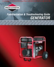
GENERATOR

You also want an ePaper? Increase the reach of your titles
YUMPU automatically turns print PDFs into web optimized ePapers that Google loves.
Portable Generator Familiarization & Troubleshooting Guide<br />
Section 2 • Generator Components & Systems<br />
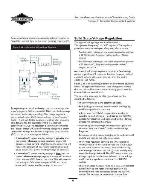
Some generators employ an electronic voltage regulator to<br />
“regulate” current flow to the rotor windings (Figure 2.54).<br />
Figure 2.54 — Generator With Voltage Regulator<br />
By regulating current flow through the rotor windings, the<br />
rotor’s magnetic field is controlled.This controls the voltage<br />
developed in the stator windings.The voltage regulator<br />
senses actual stator (AC) output voltage via two “sensing”<br />
leads (11 and 22). Stator excitation winding (AC) output is<br />
also delivered to the regulator, where it is rectified<br />
(converted to DC).The regulator electronically compares<br />
the “actual” stator (AC) power winding voltage to a preset<br />
“reference” voltage and delivers a regulated direct current<br />
(DC) to the rotor windings as follows:<br />
• If actual (AC) power winding voltage is greater than<br />
the preset reference voltage, regulator action will<br />
decrease direct current (DC) flow to the rotor.This will<br />
reduce the strength of the rotor’s magnetic field and<br />
cause stator (AC) power winding voltage to decrease.<br />
• If actual (AC) power winding voltage is less than the<br />
preset reference voltage, regulator action will increase<br />
direct current (DC) flow to the rotor.This will increase<br />
the strength of the rotor’s magnetic field and cause<br />
stator (AC) power winding voltage to increase.<br />
Solid State Voltage Regulation<br />
This type of voltage regulator is often called a<br />
“Voltage-over-Frequency” or “V/F” regulator.The regulator<br />
provides a constant voltage-to-frequency characteristic:<br />
• An alternator rotating at the speed required to provide<br />
a 60 Hertz (AC) frequency will provide a 120VAC<br />
output.<br />
• An alternator rotating at the speed required to provide<br />
a 30 Hertz (AC) frequency will provide a 60VAC<br />
output, and so on.<br />
(A conventional voltage regulator provides a fixed voltage<br />
output, regardless of frequency). If output frequency is held<br />
constant, voltage will remain constant over the entire<br />
electrical load range.<br />
Figure 2.55 is an operating diagram for alternators equipped<br />
with a “Voltage-over-Frequency” type of regulator. Notice<br />
that the unit still has an excitation winding, just as was the<br />
case with direct excited units.<br />
The operating sequence for this type of unit may be<br />
described as follows:<br />
• The rotor turns at a pre-determined speed.<br />
• EMF (voltage) is induced into the stator windings by<br />
residual magnetism in the rotor.<br />
• Voltage from the120VAC output stator winding is<br />
available through Wires #11 and #22 to the 120VAC<br />
outlets.Any electrical load connected to the 120VAC<br />
outlets will complete the circuit.<br />
• Alternating current voltage and frequency signals are<br />
delivered from the 120VAC outlets to the Voltage<br />
Regulator.<br />
• Excitation winding output is delivered through wires #2<br />
and #6 and then to the voltage regulator.<br />
• The voltage regulator converts the (AC) excitation<br />
winding output to (DC) and delivers the (DC) output<br />
to the rotor via Wire #4, the (+) brush and slip ring,<br />
then through the rotor and the (-) brush and slip ring<br />
assembly through Wire #1.The (DC) output from the<br />
voltage regulator to the rotor is based on the voltage<br />
and frequency signals received from the 120VAC<br />
outlets.<br />
• Thus, the Voltage Regulator acts to increase or decrease<br />
current flow to the rotor windings based on the<br />
demands of the load connected across the 120VAC<br />
outlets.The increase or decrease in current flow<br />
38