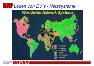
Definition and implementation of a global EV ... - Park & Charge
Definition and implementation of a global EV ... - Park & Charge
Definition and implementation of a global EV ... - Park & Charge

You also want an ePaper? Increase the reach of your titles
YUMPU automatically turns print PDFs into web optimized ePapers that Google loves.
final report<br />
Nr. contact functions sc.<br />
1 Control Pilot Vehicle detection, ground continuity checking, shut <strong>of</strong>f at the<br />
point <strong>of</strong> supply, transmission <strong>of</strong> the maximum current, detection<br />
<strong>of</strong> ventilation requirement;<br />
2 Drive train interlock<br />
If the device is used as a vehicle interface, driving should be<br />
disabled, if a charging cable is engaged.<br />
3 Data (hi) In symmetrical systems e.g. CAN-bus it will be CANH, in o-<br />
ther cases (e.g. RS232, SAE1850) the single data path.<br />
CPL<br />
4 Data (gnd) Not used with the CAN-Bus or RS 485, else signal ground DGD<br />
5 Data (lo) Only utilized with symmetrical Systems (e.g. CAN-bus,<br />
RS485)<br />
6 Power Indicator<br />
7 Power Indicator<br />
The Power Inticator provides ampacity information for the on<br />
board charger in case <strong>of</strong> mode 1 charging (no pilot provided).<br />
If it is left open, the default current will be 16A.<br />
Ground path <strong>of</strong> the Power Indicator (ELV, near to PE)<br />
Table 10: Additional auxilary contacts <strong>and</strong> their function<br />
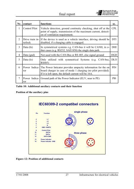
Position <strong>of</strong> the auxilary pins<br />
DTI<br />
DHI<br />
DLO<br />
PIN<br />
PI0<br />
IEC60309-2 compatibel connectors<br />
Pin<br />
Function<br />
single phase<br />
25°<br />
4<br />
5<br />
6<br />
7<br />
8<br />
L1<br />
L2<br />
L3<br />
N<br />
GND / EARTH<br />
10<br />
12<br />
11<br />
6<br />
8 7<br />
9 14 13<br />
CONNECTOR<br />
115°<br />
140°<br />
11<br />
12 10<br />
7 6<br />
13 8<br />
14 9<br />
PLUG<br />
9<br />
10<br />
11<br />
12<br />
13<br />
14<br />
Control Pilot<br />
DATA+<br />
DATA-<br />
DATA GND<br />
Power Indicator<br />
Power Indicator GND<br />
72°<br />
12<br />
10 5 6 11<br />
4 7<br />
8<br />
13<br />
9 14<br />
135°<br />
CONNECTOR<br />
155°<br />
three phase<br />
11<br />
PLUG<br />
6<br />
12<br />
5<br />
7 4<br />
8<br />
13<br />
14<br />
9<br />
10<br />
Figure 12: Position <strong>of</strong> additional contacts<br />
17/01/2008 27 Infrastructure for electrical vehicles