Sound Application Guide: - WaterFurnace
Sound Application Guide: - WaterFurnace
Sound Application Guide: - WaterFurnace

Create successful ePaper yourself
Turn your PDF publications into a flip-book with our unique Google optimized e-Paper software.
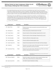
SOUND APPLICATION GUIDE: DESCRIPTION AND RATINGS<br />
Acoustical Installation Considerations<br />
<strong>WaterFurnace</strong> product today employs several technologies<br />
to reduce noise. They may include scroll compressors,<br />
variable speed fan motor with oversized blower, dual<br />
compressor isolation mounting plate, compressor blankets<br />
and multi-density base plates, and finally multi-density<br />
fiberglass insulation.<br />
The following figure illustrates some of the installation<br />
acoustic considerations that should be considered.<br />
Recommendations for Noise Reduction<br />
Horizontal Unit Location<br />
• Specify equipment with quietest sound power ratings<br />
• Do not locate units above areas with a required NC-40<br />
or less<br />
• Space WSHP at least 10 ft. (3m) apart to avoid noise<br />
summing of multiple units in a space.<br />
• Maximize the height of the unit above the<br />
ceiling (horizontal).<br />
• Suspend unit with isolation grommets that are<br />
appropriately rated to reduce vibrations (horizontal).<br />
Vertical Unit Location<br />
• Specify equipment with quietest sound power ratings<br />
• Space WSHP at least 10 ft. (3m) apart to avoid noise<br />
summing of multiple units in a space.<br />
• Acoustic ceiling coatings can greatly reduce noise levels<br />
in mechanical rooms.<br />
• Mount unit on a sound absorbing pad, extruded<br />
polystyrene, rubber or cork pad.<br />
Ductwork<br />
• Ensure return air grilles will not allow line of site noise to<br />
transfer to adjacent space. Use a sound barrier or some<br />
other material to isolate the grille from the unit. A supply<br />
grille, boot and short piece of flex duct pointed away<br />
from the unit can greatly attenuate equipment noise.<br />
• Use a canvas isolation duct connector at the supply and<br />
return duct connection of the unit.<br />
• Internally line the discharge and return duct within the<br />
first 4-8 feet of unit with acoustic insulation. Install an<br />
internally lined ‘L’ shaped return duct elbow at return<br />
grille. Face the elbow away from adjacent units.<br />
• Always install at least one 90° elbow in the discharge<br />
duct to eliminate line of sight noise transmission of<br />
the blower.<br />
• Use turning vanes at all elbows and tees to<br />
reduce turbulence.<br />
• Limit supply duct velocities to less than 1000 fpm<br />
• Design and install ductwork as stiff as possible<br />
• Allow 3 duct diameters both up and down stream of<br />
the unit before any fittings or transitions are installed.<br />
• Use duct sealant on all duct joints.<br />
• Install a short (2-4 ft.) of flex duct on all branch ducts just<br />
prior to discharge boot or diffuser to reduce vibration<br />
and duct sound prior to delivery in the room.<br />
• Locate the branch duct balancing damper as far away<br />
from the diffuser as possible.<br />
• In ceiling plenum systems, install an internally lined ‘L’<br />
shaped return duct elbow at unit. Face the elbow away<br />
from adjacent units (horizontal).<br />
Figure 7: Horizontal acoustic consideration<br />
90 deg elbow<br />
on supply<br />
Sealed low<br />
velocity<br />
ductwork<br />
Turning vanes<br />
at elbows and<br />
Tees<br />
Branch<br />
damper<br />
upstream<br />
Flex duct<br />
at diffuser<br />
2-4 ft<br />
Locate return grille<br />
6 ft from unit<br />
Acoustic lining<br />
to elbow<br />
Locate units over<br />
hallways where<br />
possible<br />
Flexible water<br />
and electrical<br />
connections<br />
Canvas<br />
connector<br />
Insulated Return<br />
(optional)<br />
Supply grille<br />
with 2-3 ft of<br />
flex left open<br />
for return air<br />
9