Exalto windshield wiper
Exalto windshield wiper
Exalto windshield wiper

You also want an ePaper? Increase the reach of your titles
YUMPU automatically turns print PDFs into web optimized ePapers that Google loves.
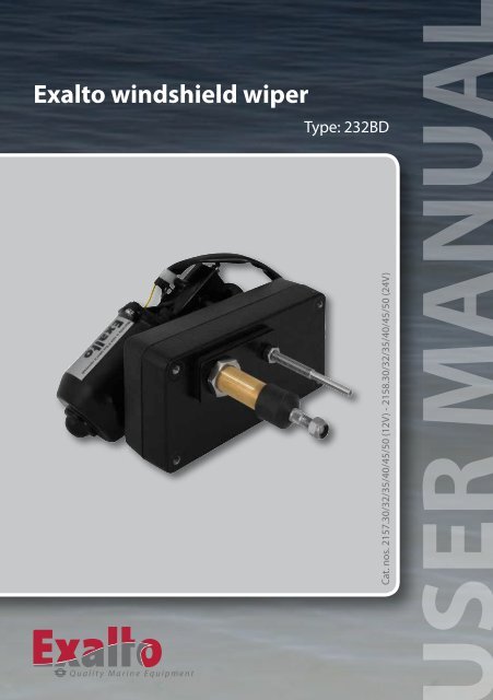
<strong>Exalto</strong> <strong>windshield</strong> <strong>wiper</strong>Type: 232BDCat. nos. 2157.30/32/35/40/45/50 (12V) - 2158.30/32/35/40/45/50 (24V)Quality Marine Equipment
Safety!!!<strong>Exalto</strong> <strong>windshield</strong> <strong>wiper</strong>s are easy to install, yet a fair amount of technicalknowledge (mechanical and electrical) is required of the installer. Pleaseconsult the manual or contact your vendor in case of doubt during installationor malfunctioning.Safety symbolsAn exclamation mark in front of the text warns you, that injury or damage canoccur if a procedure is badly performed.DangersThe installation and use of <strong>Exalto</strong> <strong>wiper</strong>s will not inflict any personal dangers ordamage, provided that installation is done according to the proceduresspecified in the manual.• Never remove covers or other safety provisions, unless maintenance is beingperformed and all safety requirements are obeyed.• The installer must provide all necessary covers.• Always disconnect the electrical circuit when performing maintenance.Prevent the installation from being started (accidentally) by others.Safety provisionsThe safety provisions will protect the user against contact with moving,electrical or hot parts. Some of them have to be provided by the installer. Thereare several safety provisions:• Cover or panel (obligatory): covers moving parts and electrical connections.The installer MUST provide a self-made cover or place the <strong>wiper</strong> behind apanel.• Make sure the <strong>wiper</strong> has enough ventilation when placing it behind a panelor cover.• Place a fuse (see specifications) in the main cable.Safety requirementsBefore the <strong>Exalto</strong> <strong>wiper</strong> is installed, we strongly recommend the following:• Read the entire manual before installation.• Make sure your working environment as well as the <strong>wiper</strong> parts are clean.• Check to be sure no parts are missing or damaged.• Use only high quality tools and have them within reach when installing.• Handle the parts with care.2
!• Never install or maintain the <strong>wiper</strong> with the electrical voltage applied, unlessthis is specifically mentioned in the manual.• Clear your tools after installation.Use of the manualRead the entire manual before installation. In this manual you can find thefollowing expressions and symbols:Hint!Gives you advice on how to perform a task more easily.Attention!Alerts you to possible problems and safety warnings.3
Contents1 Introduction ........................................................... 51.1 Introduction ...................................................... 51.2 Environmental factors ............................................. 51.3 Modified use and guarantee conditions ............................ 52 Technical data ......................................................... 62.1 General ........................................................... 62.2 Electrical data 12 Volt. ............................................. 62.3 Electrical data 24 Volt. ............................................. 62.4 Mechanical data. .................................................. 63 Installation ............................................................ 73.1 Preparation ....................................................... 73.2 Installation of mechanical parts .................................... 73.3 Electrical installation .............................................. 83.4 Final installation. .................................................. 94 Operation and use. ...................................................114.1 Preparation for first use ...........................................114.2 Use ..............................................................115 Maintenance. .........................................................125.1 General maintenance. ............................................125.2 Servicing. ........................................................125.3 Changing the wipe arc and park position. .........................125.4 Rough determination of wipe arc and <strong>wiper</strong> blade. ................135.5 Disassembly and assembly .......................................146 Troubleshooting. .....................................................157 Declaration of conformity ............................................168 Parts list ..............................................................179 Drawings and schemes ...............................................189.1 Assembly overview. ..............................................189.2 Internal wiring diagram. ..........................................194
1 Introduction!With this user manual we want to guide youin the installation and use of the <strong>Exalto</strong><strong>windshield</strong> <strong>wiper</strong>. Please follow allinstructions and install all safety provisions.1.1 Introduction<strong>Exalto</strong> <strong>windshield</strong> <strong>wiper</strong>s are especiallydesigned to keep working even with themost extreme weather conditions at sea. Allexternal parts are made of corrosion resistant materials. The housing of theself-lubricating bearings is made of bronze.Wiper type 232BD is designed to be mounted in the bulkhead or in the glasswindow. The <strong>wiper</strong> arc is adjustable from 40° to 90° with steps of 5°. Standardthe 232BD is supplied for a bulkhead thickness of either 20, 35, 55, 75, 100 or125. The matching <strong>Exalto</strong> PU pantograph arms are adjustable in length, to setthe wipe area accurately. The motors of the 232BD have insulated earth return.1.2 Environmental factorsIn the <strong>wiper</strong>, materials are used that are harmful for the environment (e.g.copper). The parts of the <strong>wiper</strong> can be re-used or recycled. No harmfulsubstances are disseminated when using or disassembling the <strong>wiper</strong>.1.3 Modified use and guarantee conditionsAll modifications or defects in the product are subject to the Orgalime GeneralConditions of Sale. Please contact your vendor in case of any questions or if youwant to use <strong>Exalto</strong> <strong>wiper</strong>s in a non-maritime environment or other applications.5
2 Technical data2.1 General• Product ........................................ <strong>Exalto</strong> <strong>windshield</strong> <strong>wiper</strong>• Types ............................................ 232BD –12 and 24 Volt• Catalogue numbers 12V ....................... 2157.30/32/35/40/45/50• Catalogue numbers 24V ....................... 2158.30/32/35/40/45/502.2 Electrical data 12 Volt• Torque (max.) ..................................................... 32 Nm• Voltage ...........................................................12 Volt• Current .............................................................3.0 A• Power consumption (max.) ..........................................36 W• Number of revolutions ......................... Low 38 rpm, high 56 rpm• Recommended cable ................. 5 wires, 1½ (16 g) or 2½ mm 2 (14 g).....................................................up to 10 m long• Recommended fuse .......................................6 A slow blow• Grounding ........................................Insulated earth returnElectrical data 24 Volt• Torque (max.) .................................................... 32 Nm• Voltage .......................................................... 24 Volt• Current ............................................................ 1.5 A• Power consumption (max.) ......................................... 36 W• Number of revolutions ......................... Low 38 rpm, high 56 rpm• Recommended cable ................ 5 wires, 1½ (16 g) or 2½ mm 2 (14 g).....................................................up to 10 m long• Recommended fuse ...................................... 4 A slow blow• Grounding .........................................Insulated earth return2.3 Mechanical data• Dimensions ............................... l x w x h = 196 x 104 x 119 mm• Shaft diameters ................. Drive shaft Ø 20 / support shaft Ø 8 mm• Mounting ....................................Through glass or bullkhead• Bearing .................................. Bronze housing, self-lubricating• Wiperarms ...................................... Model PU up to 750 mm• Wiperblades .............................................. Up to 800 mm• Wipe arc ...........................Wipe arc disc 40°-90° adjustable per 5°• Weight ................................................... approx. 2.5 kg6
3 InstallationRead the chapter on safety. Check before installation if the parts are all presentand undamaged. In case of errors, contact your vendor.3.1 PreparationThe complete <strong>wiper</strong>, with packaging, can be handled and transported by hand.Leave the <strong>wiper</strong> in the packing, until you are ready to install it; this to reducethe risk of damage. Make sure all parts, tools and other means are ready.3.2 Installation of mechanical parts1. If your <strong>wiper</strong> is supplied with the wipe arc disc uninstalled, please followsteps described in paragraphs 5.3 and 5.4 to set the wiping arc prior toinstallation.Determine the place where the <strong>wiper</strong> is to be installed. The dimensions areshown below. The <strong>wiper</strong> can be installed in any position.7
!!4. Connect the <strong>wiper</strong> to the ship’s electrical installation; see the diagramabove (or refer to paragraph 9.2 for full details on the wiring). Use a cablewith 5 wires with diameter of at least 1½ mm 2 (16 g) up to a maximumlength of 10 m. Use larger diameters when using longer cables.5. Fit a slow blow fuse of 6A(12Volt), 4A (24 Volt) in the main cable.6. Connect the switch to the <strong>wiper</strong> (refer to that specific manual forinstallation).3.4 Final installation7. Switch on the power and test the motor briefly. Wait until the motor stopsafter turning off the switch. The motor will be in park position. Thestandard park position is shown in the figure under point 8.Hint!If you have doubts regarding the park position,make a vane with tape to simulate the position ofthe arms.Attention!The 232BD is suitable for <strong>wiper</strong> arms model PU up to750 mm and <strong>wiper</strong> blades up to 800 mm.8. Place the <strong>wiper</strong> arm with the blade on theshafts. Fasten the nuts loosely onto the shafts.tapeTightening torque: 16.3Nm / 12ft.lbs9
!AttentionTo ensure the arm has the right spring pressure, install the <strong>wiper</strong> arm in such a waythat the shafts make a 90° angle with the window (figure left) and that the shaftsmake a 90° angle with the <strong>wiper</strong> arm (figure right). If this is not the case, pleaseinstall a spacer or multiple spacers to make the 90° angles.9. Switch on the power and test the motor briefly again to check the wipedarea.10. If the wipe arc is correct, adjust the position and the length of the arm ifnecessary. Tighten the nuts properly now.10
5 Maintenance5.1 General maintenanceTo keep the <strong>Exalto</strong> <strong>wiper</strong> in good condition, you are advised to:• clean <strong>wiper</strong>, arms and blades with fresh water after every journey in salt water(to prevent salt from clogging moving parts);• never use the <strong>wiper</strong> on a dry window.5.2 ServicingAs long as the <strong>wiper</strong> system functions normally and is kept in good shape (seeparagraph 5.1), servicing the motor is not necessary. Check yearly (monthlywhen used intensively) if the <strong>wiper</strong> blades are worn. Replace blades when wornor when the blades leave many stripes across the glass. In case of failure oradjustments, have servicing done solely by qualified mechanics. In chapter 6,‘Troubleshooting’, a listing is given of possible problems and their solutions.5.3 Changing the wiping arc and park positionIf the wiped area is not optimum, you can reset both the angle and the parkposition.5.3.1 Setting wiping arc1. Disconnect the power supply!2. Remove the <strong>wiper</strong> from the bulkhead and open the housing (see 5.5.2).3. Remove the wiping arc disc from the motor shaft.4. Push the pin in the hole of the disc with the correct wiping arc (see 5.4).5. Screw the M10 nut onto the pin and fasten properly, but not too tight (max.9.78 Nm/7.21 ft.lbs) to prevent damaging the bearing.6. Slide the connection lever onto the pin and secure it by inserting theretaining ring in the groove of the pin.7. Run the motor briefly to reach parking position.8. Push the disc on the motor shaft in the desired parking position (see 5.3.2).5.3.2 Setting parking position1. Place the wiping arc disc onto the motor shaft in standard or alternativesetting.2. Make sure the disc is puton in a way that theconnection lever is in analmost straight libne wit12the pin and the centrehole of the arc disc (see drawings).Standard settingparking positionAlternativesetting
• find in the table below the vertical displacement of the blade (H);Determining the vertical displacement of the <strong>wiper</strong> bladeArmlength (L) 300 350 400 450 500 550 600 650 700 750 800 850 900 950 100040° 19 21 25 26 30 34 37 40 43 45 48 51 54 57 6045° 23 27 30 35 38 42 46 50 53 57 61 65 68 72 7650° 26 33 36 43 47 52 56 61 66 70 75 80 84 89 9455° 34 40 45 51 57 62 66 74 79 85 90 96 102 107 11360° 40 47 54 60 67 74 80 87 94 100 107 114 121 127 13465° 47 55 63 71 79 86 94 102 110 117 125 133 141 149 15770° 55 63 73 81 90 100 109 118 127 136 145 154 163 172 18175° 62 73 83 93 104 114 124 135 145 155 165 176 186 196 20780° 70 82 94 105 117 129 140 152 164 175 187 199 211 222 23485° 79 92 105 119 132 145 158 171 184 197 210 223 236 250 26390° 86 103 117 132 146 161 176 190 205 220 234 249 264 278 293Units in mmVertical displacement of the blade (H)Wipe arc!• Now the <strong>wiper</strong> blade length can be calculated:Length of <strong>wiper</strong> blade = 0.9 * 2 * (E - H)5.5 Disassembly and assemblyPrevent injuries when disassembling: disconnect the <strong>wiper</strong> from the powersupply. Keep all necessary tools within reach and remember the chapter onsafety. Provide well protected packaging, if you’re going to stock or transportthe <strong>wiper</strong> assembly.5.5.1 Removing the <strong>wiper</strong> assembly from the bulkhead1. Disconnect all the electric connections of the <strong>wiper</strong>.2. Remove the <strong>wiper</strong> arms.3. Remove the nuts and plates on the outside.4. Remove the <strong>wiper</strong> from the holes in the bulkhead.5. If you want to replace the <strong>wiper</strong>, follow chapter 3.5.5.2 Disassembling the wipe arc disc1. Disconnect all the electric connections of the <strong>wiper</strong>.2. Remove the <strong>wiper</strong> from the bulkhead; (see 5.5.1).3. Unscrew the nut on the motor shaft and remove the disc.4. For adjusting the wipe arc and replacing, follow section 5.3.5.5.3 Removing the motor from the <strong>wiper</strong> assembly1. Disconnect all the electric connections of the <strong>wiper</strong>.2. Remove the <strong>wiper</strong> arms.3. Disassemble the wipe arc disc (see 5.5.2).4. Unscrew the motor and remove it.5. When replacing, screw the motor on the housing. Follow section 5.3 toinstall the wipe arc disc in the correct position.14
!6 TroubleshootingIn this chapter, several malfunctions are mentioned combined with possiblecauses. Please leave servicing to qualified mechanics.6.1 Wiper does not work after switching on• Possible causes:1. Wiper switch is not working properly.2. Burned or incorrectly sized fuse.3. Electrical connections are wired incorrectly or might be damaged.4. The <strong>wiper</strong> motor has failed.• Solutions:1. Test and replace it. Check if the current is (and keeps being) too high.2. (See solution 1).3. Measure the voltage across the motor and check all connections if there isnone.4. Replace the motor and check for drag or a high current.6.2 Wiped area or park position is not correct• Possible causes:1. The <strong>wiper</strong> arms were placed without parking the motor first.2. The wipe arc is set wrong or changed due to high loads (e.g. springpressure of arms too high, drag).3. The wires are connected incorrectly.• Solutions:1. Remove the <strong>wiper</strong> arms. Run the motor shortly to park it and re-install thearms according to chapter 3.2. Determine the wipe arc if needed (see section 5.4) and set the wipe arcagain (see chapter 5.3).3. Check and reconnect the wiring (see the scheme in section 3.3).6.3 Motor runs, but arms do not move• Possible causes:1. Mechanical joints are loose.2. Parts are broken.3. Grooves of shafts are worn.• Solutions:1. Check if the arms are well fastened. If not, open the housing (followchapter 5) and check all joints and parts to see if they are loose, broken orworn.15
7 Declaration of conformityMANUFACTURER’S DECLARATIONIn accordance to Appendix II sub B of Directive 89/392/EEG (Machines)<strong>Exalto</strong> B.V.Nijverheidsstraat 123371 XE Hardinxveld-GiessendamThe NetherlandsTel: +31 (0)184-61.58.00Fax: +31 (0)184-61.82.00hereby declares that<strong>Exalto</strong> <strong>windshield</strong> <strong>wiper</strong> type 232BD... is intended to be built into another machine or as a component, or is to beintegrated with other machines to a machine where Directive 89/392/EEGapplies to;... does not fully comply to the requirements of mentioned Directive;... complies to the following harmonised standards:Pleasure yachts• NEN-EN-ISO 10133 Extra-low voltage D.C. installations (1997)(regarding color codes)…and declares that the sub-assembly in question shall not be set intooperation until the complete machine, into which the sub-assembly is fitted,shall be complete and conforms to all aspects of Directive 89/392/EEG.Hardinxveld-Giessendam7-3-2012 (m-d-y)16
8 Parts listNo Qua Part Dimensions Cat. no.2100.3024 /1 1 Motor2100.30122 3 Socket screw s.s. M6 x 35 2100.0553 1 Housing motor side 180 x 96 x 22 2100.9024 3 Socket screw s.s. M6 x 16 2100.0505 1 Pin M8 x 26 2100.9206 1 Arc disk Ø70 x 5 2100.9306A 1 Arc sticker 2100.9317 1 Nut M10 x 6.5 s.s. M10 x 6.5 2100.3548 1 Bearing Ø13 x 14 2100.9269 2 Flat nut s.s. M8 x 4 2100.76010 2 Retaining ring 2197.09711 1 Housing drive side 180 x 96 x 22 2100.90112 1 Support spindle bulkhead 20 mm M8 x 70 2100.446Support spindle bulkhead 35 mm M8 x 90 2100.441Support spindle bulkhead 55 mm M8 x 110 2100.447Support spindle bulkhead 75 mm M8 x 130 2100.448Support spindle bulkhead 100 mm M8 x 155 2100.44913 2 Rubber locking plate 2100.49514 1 Nut s.s. M20 2100.46015 1 Locknut s.s. M8 2100.07116 1 Weathercap Ø26 x 20 2100.36117 2 Nut M20 s.s M20 2100.35018 1 S.s. plate 2100.48519 1 Locking ring Ø12 x 4 2100.41020 2 Ring s.s. 18 x 12 x 1 2100.40021 1 Bearing shell complete bulkhead 20 mm M20 x 65 2100.326Bearing shell complete bulkhead 35 mm M20 x 80 2100.321Bearing shell complete bulkhead 55 mm M20 x 100 2100.327Bearing shell complete bulkhead 75 mm M20 x 120 2100.328Bearing shell complete bulkhead 100 mm M20 x 145 2100.32922 1 Bearing 2100.92523 1 Linking lever 110 x 24 x 12 2100.93624 1 Shaft bulkhead 20 mm Ø12 x 102 2100.364Shaft bulkhead 35 mm Ø12 x 117 2100.360Shaft bulkhead 55 mm Ø12 x 137 2100.366Shaft bulkhead 75 mm Ø12 x 157 2100.368Shaft bulkhead 100 mm Ø12 x 182 2100.37017
242222034235106/6A1772189109111213131420191817161519 Drawings and schemes9.1 Assembly overview18
9.2 Internal wiring diagramThe following diagram explains the way the <strong>wiper</strong> motor works.whiteyellow0 1 2HLPblack-bluered+BWiring diagramFunction Polarity Motor code Switch code Cablehigh speed + 53b H whitelow speed + 53 L yellowearth - 31b blackcommon leg 53e P blueself parking + 53a B red19
<strong>Exalto</strong> B.V.• P.O. Box 403370 AA Hardinxveld-GiessendamThe Netherlands• T +31 (0)184 615 800• F +31 (0)184 618 200• E <strong>wiper</strong>s@exalto.com• I www.exalto<strong>wiper</strong>s.com© <strong>Exalto</strong> B.V. 07-2012