PDF 3 Pages 36 KB - BS&B Safety Systems
PDF 3 Pages 36 KB - BS&B Safety Systems
PDF 3 Pages 36 KB - BS&B Safety Systems

You also want an ePaper? Increase the reach of your titles
YUMPU automatically turns print PDFs into web optimized ePapers that Google loves.
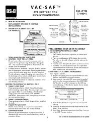
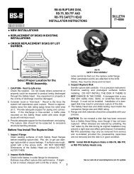
Assemble Rupture Disk and <strong>Safety</strong> Head1 . CAUTION! <strong>Safety</strong> head flanges are identical. Special attentionduring assembly and installation is required for safe installation.2 . Place new, undamaged rupture disk between safety headflanges (See Figure 1.) Place safety head flanges with theradius, R toward the disk assembly. Tighten capscrewss u fficiently to hold disk in place between the two flanges.Figure 1Install <strong>Safety</strong> HeadRupture Disks w/NameplateBurst Pressure, P1*Rupture Disks w/NameplateBurst Pressure, P2*1. Insert the FDD-7R <strong>Safety</strong> Head and rupture disk assemblybetween the companion flanges in the pressure system.After carefully reading paragraph 2, install <strong>Safety</strong> Heada s s e m b l y. Make sure <strong>Safety</strong> Head assembly is installed inthe proper direction Center the <strong>Safety</strong> Head assembly inthe companion flanges (tolerance = 1/16 inch). Selectgasket material suitable for service conditions.2. An understanding of how the D-D disk functions willavoid confusion during installation. (See Figure 1).a. Disk (1) will burst when the pressure on side Aexceeds the pressure on side B by the burst pressure,P1. Disk (1) will burst when PA-PB>P1 (i.e. Disk (1)controls overpressure on side A). Flow will be fromside Ato side B.b. Disk (2) will burst when the pressure on side Bexceeds the pressure on side A by the burst pressure,P2. Disk (2) will burst when PB-PA>P2 (i.e. Disk (2)controls overpressure on side B). Flow will be fromside B to side A .c. When either disk bursts the other disk will immediatelyreverse and burst.*P1 and P2 are the stamped burst pressures. Disks mayactually burst anywhere within the burst tolerance.3. Install companion flange studs with nuts. Tighten all nutsfinger tight before torquing. Evenly torque the studs to thevalues given in Table I. Even torque may be achieved byapplying 1/4 of desired final torque to each stud. Repeatpattern by torquing to 3/4 of desired final torque. T h e n ,using same pattern, torque to specified torque.4. The user is cautioned to select gasket materials adequatefor the service condition and ability of the gasket to resist“cold flows”. Gaskets that “cold flow” will allow torquerelaxation which will cause low bursts. Check periodicallyto assure proper torque.2SIZESAFETY HEADRATINGTYPE D-D DISKSW/PLASTIC SEALSIN ANSI FT-LBS1150 201.52346810121416182024TORQUE TABLE ITorque values for Flat Seat Type D-D Disks in Flat SeatFDD-7R <strong>Safety</strong> Head Assemblies in Foot Pounds300 40600 40150 30300 60600 60150 40300 40600 40150 40300 67600 67150 60300 100600 110150 100300 110600 165150 130300 235600 265150 160300 245600 330150 225300 305600 330150 350300 290150 345300 <strong>36</strong>0150 468300 345150 405300 375150 540300 540