Marker Band Swager.qxp - Interface Catheter Solutions
Marker Band Swager.qxp - Interface Catheter Solutions
Marker Band Swager.qxp - Interface Catheter Solutions

You also want an ePaper? Increase the reach of your titles
YUMPU automatically turns print PDFs into web optimized ePapers that Google loves.
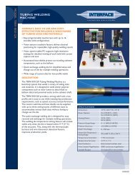
<strong>Marker</strong> <strong>Band</strong> <strong>Swager</strong>Continuous Rotation4DIE DESCRIPTION - figure 4 and 5The swaging die was designed to satisfy several key requirements, such as:a) Very high precision of all of its components in order to produce swaged partswith 0.0002 accuracy.b) Easy assembly and disassembly for purpose of die cleaning and inspection.No tools are required for die disassembly.c) Fast installation or replacement of the die in the swaging machine usingline-up pins and one screwd) Long life of the die and minimal wear of the moving parts.e) Ability to operate with no or minimal lubrication5The swaging die consists of an upper and lower part. Within the contact plane betweenthe upper and lower part lies the swaging cavity. The upper part of the die is moveablewith respect to the lower part die. Four line-up pins guide its up and down movement.The downward motion of the upper part is driven by an impact of a small heat-treatedsteel hammer that is powered by a small pneumatic cylinder. The return motion isprovided by a set of small return coil springs. Two line-up pins and a single bolt attachthe lower part of the die to the rotating gear of the swaging machine. The length oftravel, or the throw of the die, is defined by travel stops that are an integral part of thedie. The end plates contain round openings that line-up with the swaging cavity. The diecomponents are heat treated to Rc64 hardness. When assembled, all components ofthe die are held together simply by die spring pre-load force. No tools are required fordie disassembly.CAVITY FEATURESIn order to obtain good results the cavity geometry must satisfy very specific conditions.Edges of all holes, parting lines and other cavity features that come in contact with theswaged part must be rounded and polished to a mirror finish. The cavity is longitudinallysplit between the upper and lower parts of the die, thus forming a half circle groove ineach part.To achieve a smooth and uniform finish of the swaged part, the diameter reduction is asgradual as possible. Selecting an appropriate die hammering frequency and a rate of feedyields optimal results. Usually several trial runs are required to determine the bestcombination of parameters. Optimization is required, since there are some positiveand some negative aspects to the parameter selection. In general, higher hammeringfrequency and slower feed rate produce smoother surface finish. The drawback is thatslower feed rate reduces production throughput. An increase in hammering frequencycauses progressive drop-off in hammering force and that may not be acceptable forswaging stronger parts.INTERFACEASSOCIATES27752 El Lazo RoadLaguna Niguel, CA 92677Phone: 949.448.7056Fax: 949.448.7016www.interfaceusa.cominfo@interfaceusa.comRevised 2/06