Brochure - with Pulse Cross-Reference - Nuvotem Talema
Brochure - with Pulse Cross-Reference - Nuvotem Talema
Brochure - with Pulse Cross-Reference - Nuvotem Talema

Create successful ePaper yourself
Turn your PDF publications into a flip-book with our unique Google optimized e-Paper software.
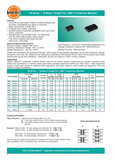
TM Series • 10 Base-T Single Port SMD Transformer ModulesFeatures• Low profile and light weight 10 Base-T modules facilitate pickand place compatability and speed of placement• Meets requirements of IEEE 802.3• Consistent and reliable coplanarity• Excellent quality at extremely competitive price due to highvolume production• Manufactured in an ISO-9001:2000, TS-16949:2002and ISO-14001:2004 certified <strong>Talema</strong> facility• Fully RoHS compliant and meets lead freereflow level J-STD-020CElectrical Specifications @ 25°CMinimum isolation voltage: 1500 VrmsOperating Temperature Range: -40°C to +85°CStorage Temperature: -40°C to +125°CQuality and consistency are guaranteed through 100% testing of the specified parameters for primary inductance, leakageinductance, turns ratio, DC resistance and interwinding capacitance.This ensures that the return loss and pulse wave shaperequirements can be fully maintained. Additionally, all parts are tested for 1500V minimum isolation.Applications<strong>Talema</strong> 10Base-T transformer modules contain transmit and receive isolation transformers to maintain consistant waveshape and suppression of common mode noise while providing equipment isolation per IEEE 802.3. High impedancecommon mode quad chokes for additional EMI suppression have been added on some models as required for FCC andCISPR 22 Class B certification.Part NumberTM__-100A1-JTM__-100A6-JTM__-112A3-JTM__-140A2-JTM__-140A3-JTM__-150A6-JTM__-200A1-JTM__-200A2-JTM__-200A4-JTM__-200A5-JTM__-140B1-JTest Frequency: Inductance, Interwinding Capacitance andLeakage Inductance measured @ 100kHz/20mVrmsStandard Packing: Tape and ReelTM Series • 10 Base-T Single Port SMD Transformer ModulesC W / W(pF Max)DCR(Ohms Max.)Turns RatioLPri. OCL L±5%(μH Max)(μH Min)1-3:16-146-8:11-9Pri/ SecPri/ Sec1-316-146-811-9V P(Vrms)Schematic1ct:1ct1ct:1ct1000.259 0.300.300.300.301500A2ct:1ct1ct:1ct1000.25120.600.300.300.301500A1ct:1ct1ct:2ct1120.308 0.300.300.300.601500A1ct:1ct1ct:1.414ct1400.20120.300.300.300.451500A1ct:1ct1ct:2ct140/250.30120.300.300.300.451500A2ct:1ct1ct:1ct1500.20120.600.300.300.301500A1ct:1ct1ct:1ct2000.20100.300.300.300.301500A1ct:1ct1ct:1.414ct2000.50150.300.300.300.451500A1ct:1ct1ct:2.5ct200/350.40150.300.300.300.801500A1ct:2ct1ct:1ct50/2000.20120.300.600.300.301500APri. Winding:Sec. WindingPri.Windings Sec. Windings1400.20121:1(4x)0.300.301500BT M__-140B2-J1:1.41(4x)1400.20120.300.451500BOrdering Information:TM * -XXX- X X-J* Specify desired Package Style “S” or “M”.“S” = Chip style surface mount, 0.100” (2,54mm) terminal spacing.“M” = Chip style miniature surface mount, 0.050” (1,27mm) terminalspacing.Example: Without choke, “S” style package and schematic “A” - TMS-100 A1Without choke, “M” style package and schematic “B” - TMM-140 B2.With choke, “S” style package, Schematic “B” - TMCS-110 B2With choke, “M” style package, Schematic”A” - TMCM-100 A1See next page for electrical specifications for modules <strong>with</strong> common mode chokes for EMInoise suppression and for packaging styles, dimensions and schematics.123678Schematics <strong>with</strong>out ChokeA1615141110912345678B161514131211109THE TALEMA GROUP • Magnetic Components for Universal Applications4