LED LCD TV SERVICE MANUAL - Jordans Manuals
LED LCD TV SERVICE MANUAL - Jordans Manuals
LED LCD TV SERVICE MANUAL - Jordans Manuals

You also want an ePaper? Increase the reach of your titles
YUMPU automatically turns print PDFs into web optimized ePapers that Google loves.
4. Manual Adjustment<br />
4.1. ADC(GP2) Adjustment<br />
4.1.1. Overview<br />
ADC adjustment is needed to find the optimum black level and<br />
gain in Analog-to-Digital device and to compensate RGB<br />
deviation.<br />
4.1.2. Equipment & Condition<br />
1) Adjust Remocon<br />
2) 801GF(802B, 802F, 802R) or MSPG925FA Pattern Generator<br />
- Resolution :<br />
480i, 720*480 (MSPG-925FA -> Model: 209, Pattern: 65)<br />
- 480i<br />
1080p, 1920*1080 (MSPG-925FA -> Model: 225, Pattern:<br />
65) - 1080p<br />
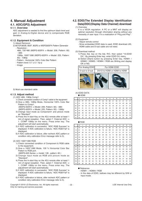
- Pattern : Horizontal 100% Color Bar Pattern<br />
- Pattern level: 0.7 ± 0.1 Vp-p<br />
- Image<br />
3) Must use standard cable<br />
4.1.3. Adjust method<br />
(1) ADC 480i, 1080p Comp1<br />
1) Check connected condition of Comp1 cable to the equipment<br />
2) Give a 480i, 1080p Mode, Horizontal 100% Color Bar<br />
Pattern to Comp1.<br />
(MSPG-925FA -> Model: 209, Pattern: 65) - 480i<br />
(MSPG-925FA -> Model: 225, Pattern: 65) - 1080p<br />
3) Change input mode as Component1 and picture mode<br />
as “Standard”<br />
4) Press the In-start Key on the ADJ remote after at least 1<br />
min of signal reception. Then, select 7. External ADC -><br />
1. COMP 1080p on the menu. Press enter key. The<br />
adjustment will start automatically.<br />
5) If ADC calibration is successful, “ADC RGB Success” is<br />
displayed. If ADC calibration is failure, “ADC RGB Fail” is<br />
displayed.<br />
6) If ADC calibration is failure, after recheck ADC pattern or<br />
condition retry calibration Error message refer to 5).<br />
(2) ADC 1920*1080 RGB<br />
1) Check connected condition of Component & RGB cable<br />
to the equipment.<br />
2) Give a 1920*1080 Mode, 100 % Horizontal Color Bar<br />
Pattern to RGB port.<br />
(MSPG-925 Series -> model: 126 , pattern: 65 )<br />
3) Change input mode as RGB and picture mode as<br />
“Standard”.<br />
4) Press the In-start Key on the ADJ remote after at least 1<br />
min of signal reception. Then, select 7. External ADC -><br />
1. COMP 1080p on the menu. Press enter key. The<br />
adjustment will start automatically.<br />
5) If ADC calibration is successful, “ADC RGB Success” is<br />
displayed. If ADC calibration is failure, “ADC RGB Fail” is<br />
displayed.<br />
6) If ADC calibration is failure, after recheck ADC pattern or<br />
condition retry calibration Error message refer to 5).<br />
Copyright © 2010 LG Electronics. Inc. All rights reserved.<br />
Only for training and service purposes<br />
- 9 -<br />
4.2. EDID(The Extended Display Identification<br />
Data)/DDC(Display Data Channel) download<br />
(1) Overview<br />
It is a VESA regulation. A PC or a MNT will display an<br />
optimal resolution through information sharing without any<br />
necessity of user input. It is a realization of “Plug and Play”.<br />
(2) Equipment<br />
- Adjust remote control<br />
- Since embedded EDID data is used, EDID download JIG,<br />
HDMI cable and D-sub cable are not need.<br />
(3) Download method<br />
1) Press Adj. key on the Adj. R/C, then select “10.EDID<br />
D/L”, By pressing Enter key, enter EDID D/L menu.<br />
2) Select [Start] button by pressing Enter key, HDMI1 /<br />
HDMI2 / HDMI3 / HDMI4 / RGB are Writing and display<br />
OK or NG.<br />
For Analog EDID<br />
D-sub to D-sub DVI-D to HDMI or HDMI to HDMI<br />
(4) EDID DATA<br />
A HDMI<br />
A RGB<br />
For HDMI EDID<br />
0 1 2 3 4 5 6 7 8 9 A B C D E F<br />
0 00 FF FF FF FF FF FF 00 1E 6D 01 00 01 01 01 01<br />
10 01 14 01 03 68 10 09 78 0A EE 91 A3 54 4C 99 26<br />
20 0F 50 54 A1 08 00 81 80 61 40 45 40 31 40 01 01<br />
30 01 01 01 01 01 01 02 3A 80 18 71 38 2D 40 58 2C<br />
40 45 00 A0 5A 00 00 00 1E 01 1D 00 72 51 D0 1E 20<br />
50 6E 28 55 00 A0 5A 00 00 00 1E 00 00 00 FD 00 3A<br />
60 3F 1E 53 10 00 0A 20 20 20 20 20 20 00 00 00 FC<br />
70 00 4C 47 20 54 56 0A 20 20 20 20 20 20 20 00 1D<br />
0 1 2 3 4 5 6 7 8 9 A B C D E F<br />
0 00 FF FF FF FF FF FF 00 1E 6D 01 00 01 01 01 01<br />
10 01 14 01 03 80 10 09 78 0A EE 91 A3 54 4C 99 26<br />
20 0F 50 54 A1 08 00 71 4F 81 01 01 01 01 01 01 01<br />
30 01 01 01 01 01 01 02 3A 80 18 71 38 2D 40 58 2C<br />
40 45 00 A0 5A 00 00 00 1E 01 1D 00 72 51 D0 1E 20<br />
50 6E 28 55 00 A0 5A 00 00 00 1E 00 00 00 FD 00 3A<br />
60 3F 1E 53 10 00 0A 20 20 20 20 20 20 00 00 00 FC<br />
70 00 4C 47 20 54 56 0A 20 20 20 20 20 20 20 01 D7<br />
80 02 03 26 F1 4E 10 1F 84 13 05 14 03 02 12 20 21<br />
90 22 15 01 26 15 07 50 09 57 07 67 03 0C 00 XX XX<br />
A0 B8 2D E3 05 03 01 01 1D 80 18 71 1C 16 20 58 2C<br />
B0 25 00 A0 5A 00 00 00 9E 01 1D 00 80 51 D0 1A 20<br />
C0 6E 88 55 00 A0 5A 00 00 00 1A 02 3A 80 18 71 38<br />
D0 2D 40 58 2C 45 00 A0 5A 00 00 00 1E 66 21 50 B0<br />
E0 51 00 1B 30 40 70 36 00 A0 5A 00 00 00 1E 00 00<br />
F0 00 00 00 00 00 00 00 00 00 00 00 00 00 00 00 XX<br />
A Reference<br />
- HDMI1 ~ HDMI4 / RGB<br />
- In the data of EDID, bellows may be different by S/W or<br />
Input mode.<br />
LGE Internal Use Only