Omron Varispeed F7 (CIMR-F7Z) (3508 Kb). - Industriale Elettrica
Omron Varispeed F7 (CIMR-F7Z) (3508 Kb). - Industriale Elettrica
Omron Varispeed F7 (CIMR-F7Z) (3508 Kb). - Industriale Elettrica

Create successful ePaper yourself
Turn your PDF publications into a flip-book with our unique Google optimized e-Paper software.
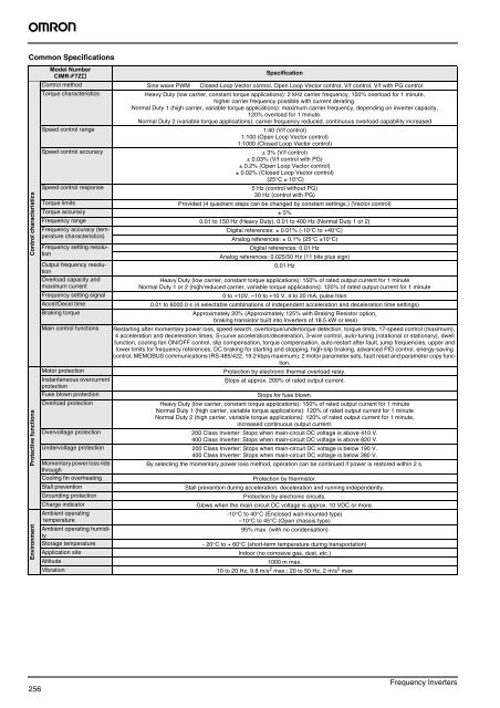
Common SpecificationsControl characteristicsProtective functionsEnvironmentModel Number<strong>CIMR</strong>-<strong>F7</strong>ZSpecificationControl method Sine wave PWM Closed Loop Vector control, Open Loop Vector control, V/f control, V/f with PG controlTorque characteristicsHeavy Duty (low carrier, constant torque applications): 2 kHz carrier frequency, 150% overload for 1 minute,higher carrier frequency possible with current derating.Normal Duty 1 (high carrier, variable torque applications): maximum carrier frequency, depending on inverter capacity,120% overload for 1 minute.Normal Duty 2 (variable torque applications): carrier frequency reduced, continuous overload capability increasedSpeed control range1:40 (V/f control)1:100 (Open Loop Vector control)1:1000 (Closed Loop Vector control)Speed control accuracy± 3% (V/f control)± 0.03% (V/f control with PG)± 0.2% (Open Loop Vector control)± 0.02% (Closed Loop Vector control)(25°C ± 10°C)Speed control response5 Hz (control without PG)30 Hz (control with PG)Torque limitsProvided (4 quadrant steps can be changed by constant settings.) (Vector control)Torque accuracy ± 5%Frequency range 0.01 to 150 Hz (Heavy Duty), 0.01 to 400 Hz (Normal Duty 1 or 2)Frequency accuracy (temperaturecharacteristics)Frequency setting resolutionOutput frequency resolutionOverload capacity andmaximum currentDigital references: ± 0.01% (-10°C to +40°C)Analog references: ± 0.1% (25°C ±10°C)Digital references: 0.01 HzAnalog references: 0.025/50 Hz (11 bits plus sign)0.01 HzHeavy Duty (low carrier, constant torque applications): 150% of rated output current for 1 minuteNormal Duty 1 or 2 (high/reduced carrier, variable torque applications): 120% of rated output current for 1 minuteFrequency setting signal0 to +10V, –10 to +10 V, 4 to 20 mA, pulse trainAccel/Decel time0.01 to 6000.0 s (4 selectable combinations of independent acceleration and deceleration time settings)Braking torqueApproximately 20% (Approximately 125% with Braking Resistor option,braking transistor built into Inverters of 18.5 kW or less)Main control functions Restarting after momentary power loss, speed search, overtorque/undertorque detection, torque limits, 17-speed control (maximum),4 acceleration and deceleration times, S-curve acceleration/deceleration, 3-wire control, auto-tuning (rotational or stationary), dwellfunction, cooling fan ON/OFF control, slip compensation, torque compensation, auto-restart after fault, jump frequencies, upper andlower limits for frequency references, DC braking for starting and stopping, high-slip braking, advanced PID control, energy-savingcontrol, MEMOBUS communications (RS-485/422, 19.2 kbps maximum), 2 motor parameter sets, fault reset and parameter copy function.Motor protectionProtection by electronic thermal overload relay.Instantaneous overcurrentStops at approx. 200% of rated output current.protectionFuse blown protectionStops for fuse blown.Overload protectionHeavy Duty (low carrier, constant torque applications): 150% of rated output current for 1 minuteNormal Duty 1 (high carrier, variable torque applications): 120% of rated output current for 1 minuteNormal Duty 2 (high carrier, variable torque applications): 120% of rated output current for 1 minute,increased continuous output current.Overvoltage protection 200 Class Inverter: Stops when main-circuit DC voltage is above 410 V.400 Class Inverter: Stops when main-circuit DC voltage is above 820 V.Undervoltage protection 200 Class Inverter: Stops when main-circuit DC voltage is below 190 V.400 Class Inverter: Stops when main-circuit DC voltage is below 380 V.Momentary power loss rideBy selecting the momentary power loss method, operation can be continued if power is restored within 2 s.throughCooling fin overheatingProtection by thermistor.Stall preventionStall prevention during acceleration, deceleration and running independently.Grounding protectionProtection by electronic circuits.Charge indicatorGlows when the main circuit DC voltage is approx. 10 VDC or more.Ambient operating-10°C to 40°C (Enclosed wall-mounted type)temperature–10°C to 45°C (Open chassis type)Ambient operating humidity95% max. (with no condensation)Storage temperature- 20°C to + 60°C (short-term temperature during transportation)Application siteIndoor (no corrosive gas, dust, etc.)Altitude1000 m max.Vibration10 to 20 Hz, 9.8 m/s 2 max.; 20 to 50 Hz, 2 m/s 2 max256Frequency Inverters