Benchmark Tests for Computer Simulated Persons
Benchmark Tests for Computer Simulated Persons
Benchmark Tests for Computer Simulated Persons

Create successful ePaper yourself
Turn your PDF publications into a flip-book with our unique Google optimized e-Paper software.
Aalborg UNIVERSITY<strong>Benchmark</strong><strong>Tests</strong><strong>for</strong> a<strong>Computer</strong><strong>Simulated</strong>PersonP.V. Nielsen, S. Murakami, S. Kato, C. Topp,J.-H.YangISSN1395-7953R0307Indoor EnvironmentalEngineeringDepartmentofBuildingTechnologyand Structural EngineeringAalborgUniversity,October 2003Sohngaardsholmsvej57,DK-9000Aalborg,DenmarkPhone:+4596358080 Fax:+45 9814 8243http://iee.civil.auc.dk
<strong>Benchmark</strong> <strong>Tests</strong> <strong>for</strong> a <strong>Computer</strong> <strong>Simulated</strong> PersonbyPeter V. Nielsen 1 , Shuzo Murakami 2 , Shinsuke Kato 3 , Claus Topp 1 and Jeong-Hoon Yang 3Version of 7 November 2003IntroductionThermal manikins without and with breathing functions have been used <strong>for</strong> many years in full-scaleexperiments concerning indoor environment problems, see Brohus and Nielsen (1996), Bjørn andNielsen (2002) and the proceedings of the International Meeting on Thermal Manikin Testingedited by Nilsson and Holmér (1999). The use of thermal manikins with breathing function makes itpossible to measure the influence of ventilation and source location within healthy buildingproblems and to measure the details of the processes involved in passive smoking, SARS infection,and many other details of the transport processes in the indoor environment.Computational Fluid Dynamics (CFD) is an alternative to full-scale measurements. Researchcentres around the world have there<strong>for</strong>e developed different configurations (subroutines) torepresent a <strong>Computer</strong> <strong>Simulated</strong> Person (CSP). The CSP´s can be very different in respect to size,<strong>for</strong>m (rectangular grid or body-fitted grid), heat emission details, turbulence models, etc. Thevariations may reflect the different possibilities in the software but it may also be because ofdifferent standards <strong>for</strong> persons from country to country. Some examples of predictions made withCSP’s are given by Murakami et al. (1995), Murakami et al. (1996), Murakami et al. (1998), Brohusand Nielsen (1996), Bjørn and Nielsen (2002) and Topp et al. (2002).Figure 1 shows different thermal manikins <strong>for</strong> experiments. They also reflect the possibilities whichcan be obtained in a CFD prediction ranging from a simple rectangular geometry to a very detailedmanikin.Figure 1. Four manikins <strong>for</strong> experiments.This note introduces two different benchmark tests <strong>for</strong> a CSP. Both test cases have been, or will be,measured in full scale to get measurements <strong>for</strong> comparison with the predictions. The measurements1 Aalborg University and International Centre <strong>for</strong> Indoor Environment and Energy2 Keio University3 University of Tokyo
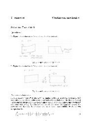
will be made with the detailed manikin shown to the right in Figure 1. This manikin has beendeveloped at DTU in Copenhagen, see Tanabe et al. (1994) and Madsen (1999).One benchmark test will be related to mixing ventilation and another test to displacementventilation. The mixing ventilation case has been developed by Aalborg University within theframework of the International Centre <strong>for</strong> Indoor Environment and Energy, and the displacementventilation case has been developed at the University of Tokyo and Keio University.Mixing Ventilation CaseThe CSP considered in this case is seated and it is facing a unidirectional flow field that may beconsidered similar to the flow field a person is exposed to in a mixing ventilated room, as illustratedin Figure 2.Figure 2. A person is exposed to a flow field in a mixing ventilated room that locally may beconsidered as a uni<strong>for</strong>m flow.The uni<strong>for</strong>m flow field is simulated as a horizontal flow in a wind tunnel, see Figure 3. Thisgeometry is equivalent to the set-up in the experiments discussed at the end of this note.The width of the tunnel is 1.2 m. Both the CSP and the exhaust openings are centred on the x-axis.The circular exhaust openings have a diameter of 0.25 m and are located 0.6 m from the floor andthe ceiling, respectively. Top, sidewall, floor and end wall should be simulated as solid surfaces.2.46 my0.7 mx2.44 mFigure 3. Plane outline at z = 0 of the tunnel and location of the CSP. The CSP is seated in themixing ventilation case and facing the flow. The width of the tunnel is 1.2 m.A uni<strong>for</strong>m velocity u o is applied at x = 0 (to the left in Figure 3), while the air leaves through thetwo circular openings at the opposite end (to the right in Figure 3). The two outlet openings may besimulated as partly squared openings if the CFD program is restricted to the use of Cartesian grid.2
Numerical Methods and Boundary ConditionsThe inlet boundary conditions have the following values:U o(m/s)T o(°C)k o(m 2 /s 2 )ε o(J/kgs)Case 1 0.05 22 6.0E-04 4.8E-06Case 2 0.20 22 9.6E-03 3.1E-04Case 3 0.50 22 6.0E-02 4.8E-03The turbulent kinetic energy and the dissipation of turbulent kinetic energy have been calculatedfrom3/ 223/ 4 koko= 1.5( uoIo) and εo= Cµlowith turbulence intensity I o = 40% (based on Nielsen 1990) and turbulent length scale l o = 0.5 m(based on Gosman et al. 1980).The boundary conditions at the floor are given as surface concentration c s of 1000 mg/m 3 with adensity of ρ = 1.2 kg/m 3 .CFD codeTurbulence model:Algorithm:SchemeGrid (<strong>for</strong>mat, number):Combined simulation ofair flow and radiation:<strong>Computer</strong> <strong>Simulated</strong> Person (CSP)Posture:Geometry:Heat flux:Breathing:freefreefreefreefreeseatedfree76 W, corresponding to an activity level of 1 met. The feetare in contact with the floor but there is no heat flux fromthe feet to the floor. The Heat flux is 38 W if onlyconvection is includedfreeGridThere are no restrictions on the grid. The specification of the grid should be indicated or reported.Quality of the CFD predictionComments should be made on the quality of the predictions as:• Order of accuracy of the numerical scheme• Turbulence model3
• Grid quality should be considered and studied i.e. in terms of different grid sizes ordistribution of y + -valuesResultsThe predictions must be made <strong>for</strong> the individual <strong>Computer</strong> <strong>Simulated</strong> Person used by theparticipants of the benchmark test.It is convenient to report the simulations at the following locations:• Vertical velocity profiles at different positions along the x-axis (z = 0): x = 0.19 m,x = 0.69 m, x = 1.19 m, x = 1.69 m and x = 2.19 m• Three horizontal velocity profiles(m/s) close to the manikin. The first profileshould be located 25 mm above the head. The second profile should be located atthe centre of the mouth, and the last profile should be at the height of the torso(158 mm above the upper part of the legs)• Concentration gradients (kg/kg) at different positions along the x-axis (z = 0): x =0.19 m, x = 0.69 m, x = 1.19 m, x = 1.69 m and x = 2.19• Horizontal concentration profile (kg/kg) at the centre of the mouth and inhaledconcentration• Average convective heat transfer coefficient (W/m 2 o C)If combined simulation of air flow and radiation is considered, the convective and radiative heattransfer rate of each region should be reported:• Area of each region (m 2 )• Convective and radiative heat transfer rate (W/m 2 )Displacement Ventilation CaseThe CSP considered in displacement ventilation is standing and facing the supply flow as shown infigure 4. It is placed 5 cm above the floor to avoid heat conduction from the CSP to the floor.yxz4
Figure 4. Set-up of the displacement ventilation case. The CSP is standing in this case in the meanplanes of the room.Air is supplied from an opening with dimensions 0.4 m (width) and 0.2 m (height) located at thefloor and centred on the x-axis. The exhaust opening has the same dimensions and is located at theceiling and centred on the x-axis.Numerical Methods and Boundary ConditionsThe inlet boundary conditions are as follows:Velocity 0.2 m/s (air flow rate 0.016 m 3 /s)Temperature 22ºCTurbulence intensity 30%Turbulent length scale 0.1 mThe boundary conditions at the floor are given as surface concentration c s of 1000 mg/m 3 with adensity of ρ = 1.2 kg/m 3 .CFD codeTurbulence model:Algorithm:Scheme:Grid (<strong>for</strong>mat, number):Combined simulation ofair flow and radiation:<strong>Computer</strong> <strong>Simulated</strong> Person (CSP)Posture:Geometry:Heat flux:Breathing:freefreefreefreefreestanding, 5 cm above the floorfree76 W corresponding to an activity level of 1 met. The feetare free of the floor and there will be a heat flux from thesoles of the feet. The heat flux is 38 W if only convection isincludefreeGridThere are no restrictions on the grid. The specification of the grid should be indicated or reported.Quality of the CFD predictionComments should be made on the quality of the predictions as:Order of accuracy of the numerical schemeTurbulence modelGrid quality should be considered and studied i.e. in terms of different grid sizes ordistribution of y + -values5
ResultsThe results should be reported at the following locations (see figure 5):• Vertical velocity, concentration, and temperature profiles at L1, L2, L4 and L5(m/s, kg/kg and o C )• One vertical velocity ant temperatur profile above the head, L3 (m/s and o C )• One horizontal velocity, concentration, and temperature profile located at thecentre of the mouth, L6 (m/s, kg/kg and o C )• Inhaled concentration (kg/kg )• Average convective heat transfer coefficient (W/m 2 o C)Figure 5. Locations of lines <strong>for</strong> reporting results.If combined simulation of air flow and radiation is considered, the convective and radiative heattransfer rate of each region should be reported:• Area of each region (m 2 )• Convective and radiative heat transfer rate (W/m 2 )Measurements <strong>for</strong> Comparisons in the Mixing Ventilation CaseVelocity measurements have been made in the mixing ventilation case and they can be downloadedin an Excel spreadsheet from www.civil.auc.dk/~i6topp/CSP.LiteratureA. D. Gosman, P. V. Nielsen, A. Restivo and J. H. Whitelaw, The Flow Properties of Rooms WithSmall Ventilation Openings. Journal of Fluids Engineering, Vol. 102, pp. 316-323, 1980.C. Topp, P. V. Nielsen and D. N. Sørensen, Application of <strong>Computer</strong>-<strong>Simulated</strong> <strong>Persons</strong> in IndoorEnvironmental Modeling. ASHRAE Transactions 2002, Vol. 108, Pt. 2, 2002.E. Bjørn and P. V. Nielsen, Dispersal of Exhaled Air and Personal Exposure in DisplacementVentilated Rooms. Indoor Air, Vol. 12, No. 3, pp. 147-164, 2002.6
H. Brohus and P. V. Nielsen, CFD Models of <strong>Persons</strong> Evaluated by Full-Scale Wind ChannelExperiments. In: ROOMVENT’96: Proceedings of the 5th International Conference on AirDistribution in Rooms, Yokohama, Japan, July 17-19, 1996.H. Brohus and P. V. Nielsen, Personal Exposure in Displacement Ventilated Rooms. In: Indoor Air:International Journal of Indoor Air Quality and Climate. - 1996: Vol. 6, No. 3. - pp 157-167.P. V. Nielsen, Specification of a Two-Dimensional Test Case. IEA Annex 20 Report, AalborgUniversity, ISSN 0902-7513 R9040, 1990.H. O. Nilsson and I. Holmér, The Third International Meeting on Thermal Manikin Testing at theNational Institute <strong>for</strong> Working Life, Sweden, October 12-13, 1999.S. Murakami, S. Kato and J. Zeng, (1995), Development of a Computational Thermal Manikin –CFD Analysis of Thermal Environment around Human Body. Proceedings of Tsinghua HVAC-’95,Beijing, Vol. 2, pp. 349 – 354.S. Murakami, S. Kato and J. Zeng, (1996), CFD Analysis of Thermal Environment around HumanBody. Proceedings of INDOOR AIR ’96, The 7th International Conference on Indoor Air Qualityand Climate, Vol. 2, pp. 479 – 484, July 21 – 26, Nagoya, Japan.S. Tanabe, E. E. A. Arens, F. S. Bauman, H. Zhang, T.L. Madsen, 1994, Evaluating ThermalEnvironments by Using a Thermal Manikin with Controlled Skin Surface Temperature. ASHRAETransactions, Part 1.S. Murakami, S. Kato and J. Zeng, 1998. Combined simulation of airflow, radiation and moisturetransport <strong>for</strong> heat release from human body, P6th International Conference on Air Distribution inRooms, ROOMVENT ´98, Stockholm, Sweden, vol. 2, pp. 141-150.T. L. Madsen, 1999. Development of a Breathing Thermal Manikin, Proceedings of the ThirdInternational Meeting on Thermal Manikin Testing, 3IMM, National Institute <strong>for</strong> Working Life,Stockholm.7