Handic VIC-REL Manual - Bombjack.org
Handic VIC-REL Manual - Bombjack.org
Handic VIC-REL Manual - Bombjack.org
- No tags were found...

You also want an ePaper? Increase the reach of your titles
YUMPU automatically turns print PDFs into web optimized ePapers that Google loves.
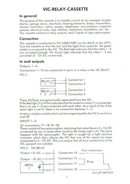
In gene ral<strong>VIC</strong>·<strong>REL</strong>A Y ·CASSETTEThe purpose ol lhis cossette is 10 simplify conlrol of, fo r example, burglaralarms, garage doors, doorlocks. healing elements, lomps. tra nsmitters,remote controllers, valves. pumps, telephones, accumulators. irrigolionsystems, electricol too ls, slo p walches, ventila tors, hum id ifiers, etc, etc.The cossette conta ins 6 re lo y outpu ts, and 2 inpuls of type o ptacoup le r.ConnectionTh is cassette is connected 10 <strong>VIC</strong>-USER-PORT (on Ihe BACK 10 the LEfT).Turn Ihe cossette so tha I Ihe le.-I and the lights face upwards. The greensocke t is connected to the <strong>VIC</strong>. The Red lig ht indicates tho t Ihe inlets 1-6ore octiva ted (closed ). The Green light indica tes Ihol Ihe inlets 1-2 oreoctivated (5-12v DC connected).In and outputsOutputs: 1- 6.Connections 1- 12 are connected in pairs to a re lay in the <strong>VIC</strong> <strong>REL</strong>AY.FIG· l .\RE; AY?oI"~AY/o~ , Connection 10Connection 2I0 , Connection 30Connection 4IThese OUT puts ore galvanically separa ted fr om the <strong>VIC</strong>.If the Red light (1) is lit this indicates thaI the socket on re lay (1) is connected,that is to soy 1-2 a re contacted with each o ther. As a result of this if thesome light is nat lit, there is no connectio n between 1-2.A re la y is simply a switch which can be programmed by the <strong>VIC</strong> to sw itc h onand off.IN PU TS 1- 2Or connections 17-18 19- 20.These constist of two optocouplers, indicating that when the re is 5-1 2v DCconnected by you to some o ther machine the Green light is lit. The samehappens with the optocoupler. The light is caught by 0 light sensi tivetransistor which then informs the <strong>VIC</strong> that one of the inpu ts has beenconnected to 5-12v DC. This is to ensure that a ll your connections to the<strong>VIC</strong>·userport a re isolated.FIG·2. <strong>VIC</strong>·<strong>REL</strong>A YIYo ur con nec tion.\Output +5v DC -(+) _ Connection 14 >o utput -5v DEt=C- (-J-t Connection 15 -.--]-SI:::-tOPTO. III I-I-j Co""eol,oo 17 cop L,. 1 _ (+)-0 Connectio n 18 __ < ____---'0\IO nl off SWITCH